Theory of Operation Section 4
4-3
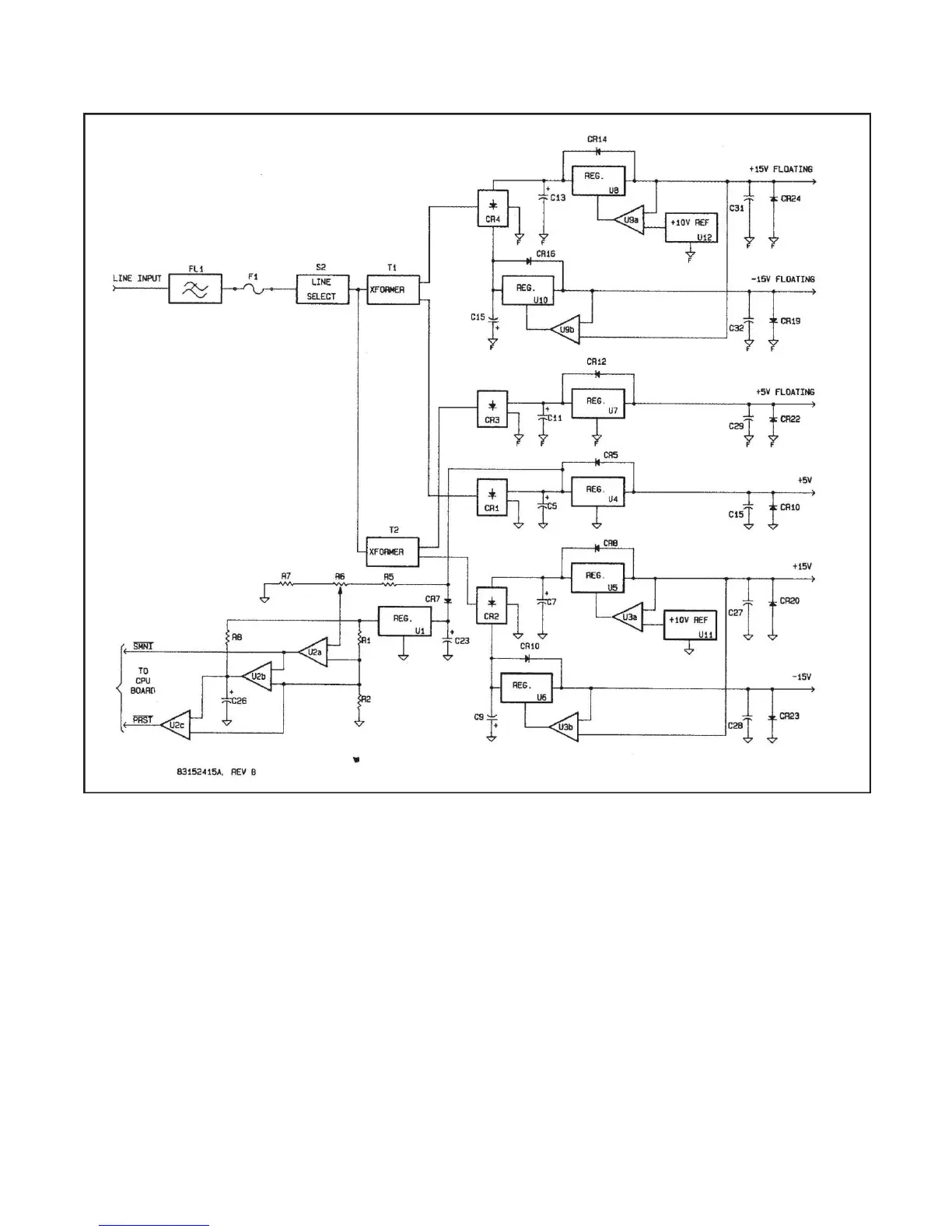
Figure 4-2. Power Supply Circuits Block Diagram.
4-14. DETAILED CIRCUIT DESCRIPTION.
4-15. A11 Power Supply Circuits. The power supply
provides the main power for the logic and analog circuits.
Refer to Figure 4-2.
4-16. Line power is connected to transformers T1 and
T2 via line filter FL1, fuse F1, and line voltage selector
switch S2. FL1 keeps internally generated RF signals
from appearing on the power connecting cable thus pre-
venting unwanted electromagnetic radiation. Line switch
S2 alters the connections to the primaries of T1 and T2
allowing the Model 1121A to operate from line voltages of
100 to 240 volts. The dual power supplies provide fixed
and floating sources of +5, +15 and -15 volts. The fixed
and floating supplies are essentially identical; therefore,
only one will be described in detail.
4-17. One of the two secondary windings on T1 is con-
nected through full-wave bridge CR1 to regulator U4. This
regulator generates a +5 volt regulated voltage for logic
circuits. Capacitor C5 provides the essential energy
storage which reduces the ripple voltage at the input of
U4. C15 provides local bypassing of the regulator circuits
and diodes CR5 and CR10 protect the integrated
regulator from reverse power.


 To Next Page