EN
16
Installation
www.bora.com
4 Installation
Observe all safety and warning information (see the
Safety chapter).
Follow the enclosed manufacturer’s information.
4.1 General installation information
INFO The appliances must not be installed above
cooling devices, dishwashers, stoves, ovens,
washing machines or dryers.
INFO The contact surfaces of the worktops and wall
sealing strips must be made of a heat-resistant
material (up to approx. 100 °C).
INFO Worktop cut-outs must be moisture-sealed using
suitable means and, where necessary, fitted with
a thermal insulator.
INFO External devices may only be connected to the
cooktop extractor connections provided.
4.1.1 Operating the cooktop extractor with
a fireplace that depends on the air in
the room
INFO
The state and regional laws and regulations must be
observed with regard to the exhaust duct design.
INFO A sufficient air supply must be ensured.
Fireplaces that depend on the air in the room (e.g. gas,
oil, wood or coal-fired heaters, continuous-flow water
heaters, instantaneous water heaters) draw in air from
the room in which they are installed and release the
exhaust fumes into the outside air via an exhaust system
(e.g. chimney).
If the cooktop extractor is used in exhaust mode, it draws
in air from the room in which it is installed as well as from
neighbouring rooms. Without sufficient air, there will be a
drop in air pressure. Toxic gases could be drawn out of the
chimney or extraction ducting and back into the room.
Fig. 4.1 Exhaust air installation – not permitted
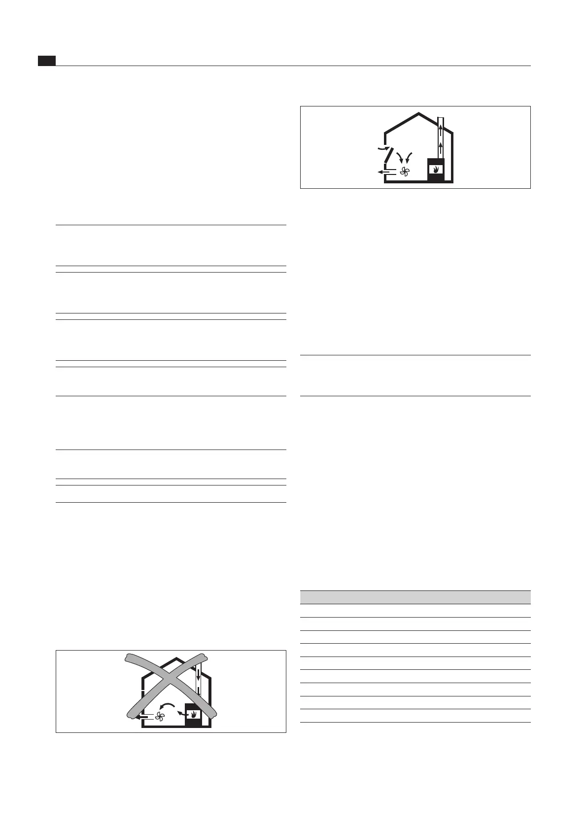
Fig. 4.2 Exhaust air installation – correct
If simultaneously operating both a fireplace and the
cooktop extractor in the same room, ensure that:
the maximum low pressure is 4 Pa (4 x 10⁻⁵ bar);
a safety device (e.g. window contact switch, low
pressure warning device) is used to ensure that a
sufficient supply of fresh air is guaranteed;
the exhaust air is not be ducted into a chimney that
is used for exhaust gases of devices operated with
gas or other combustibles;
the installation is checked and approved by an
authorised certified engineer (e.g. heating engineer).
INFO No window contact switches may be installed that
separate the control unit from the power supply
(phase separation). Only the interface is to be used.
4.2 Checking the delivery
Check the scope of delivery for damage and make sure
it is complete.
If there are any missing or damaged parts, please
notify BORA After Sales Service.
Do not under any circumstances install parts which are
damaged.
Dispose of transport packaging in the proper manner
(see the Decommissioning, disassembly and disposal
chapter).
4.2.1 Scope of delivery of the cooktop
extractor
Scope of delivery CKA2 Quantity
Installation instructions 1
Operating instructions 1
Extractor base module (CKA2GM) 1
Air inlet nozzle (CKA2ED) 1
Grease filter unit (CKA2FFE) 1
Control unit (CKA2SB) 1
Power supply cable (country-specific) 1
Flexible module (CKA2MF) 1
Ferrite sleeve (UFK) 1
Tab. 4.1 Scope of delivery of the cooktop extractor
 Loading...