EN
21
Installation
www.bora.com
Assemble the adapter panel:
Position the connection module [3] facing the left or
right depending on the planned installation option.
Check that the adapter panel [2] seal is positioned
correctly.
Position the adapter panel [2] in such a way that the
duct connection is facing left or right as required.
Insert the adapter panel [2] into the connection
module [3] from above.
To do this, slide the adapter panel into the slots on the
connection module [3].
Do not use force to assemble the parts.
Ensure that the lock clicks into place.
Assemble the base module:
Place the base module [1] on top of the connection
module [3] with its adapter panel [2] already fitted.
Do not use excessive force to assemble the parts.
Ensure that the lock clicks into place.
Check that all components are positioned correctly.
Check that the clearance inside the extractor is even.
4.9 Installing the cooktop extractor
INFO Clearance of one millimetre should be planned
between the appliances.
INFO In the case of flush installation, a clearance of
two millimetres should be planned around the
appliances.
Cross bars on the kitchen unit in the area of the
worktop cut-out may need to be removed.
The drawers and/or shelves in the floor unit must be
removable for maintenance and cleaning purposes.
A return flow aperture > 500 cm² is required in the
kitchen units for recirculation systems (e.g. by shortening
the plinth boards or using suitable slatted plinths).
Make sure that the area at the front of the floor unit is
sufficiently ventilated with clean air.
Make sure that the floor unit is not soiled by the
ventilation openings.
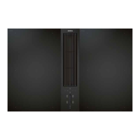
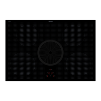
4.8.1 Assembling cooktop extractor CKA2
There are two different models of cooktop extractor
CKA2, depending on the planned airflow:
1
2
Fig. 4.16 Assembled cooktop extractor CKA2
[1] Cooktop extractor CKA2 for airflow towards the right
[2] Cooktop extractor CKA2 for airflow towards the left
INFO If the adapter panel is fitted correctly, the duct
connection will always be at the front on both
models (facing the user).
INFO You can check that the adapter panel has been
fitted correctly by looking at the arrow markings
on the panel and the base module. These must be
correctly aligned.
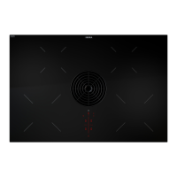
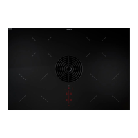
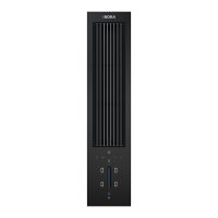
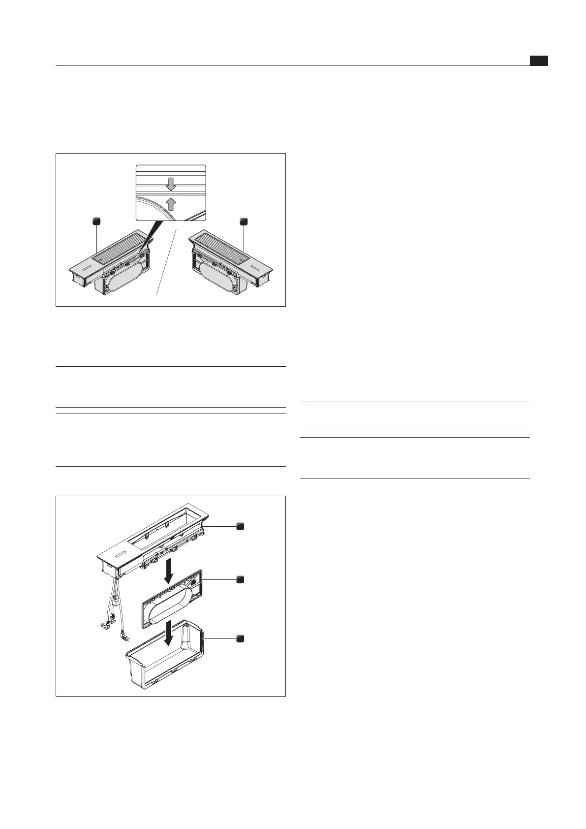
Assembling the individual components
3
2
1
Fig. 4.17 Assembling the individual components on cooktop
extractor CKA2
[1] Extractor base module
[2] Adapter panel with O-ring seal
[3] Connection module
 Loading...