6 720 220 045
Revised 01-11 Subject to change without prior notice
TABLE OF CONTENTS
Model Nomenclature .................................................................................... 3
Initial Inspection .......................................................................................... 4
General Description ..................................................................................... 4
Moving and Storage ..................................................................................... 4
Safety Considerations .................................................................................. 4
Location ....................................................................................................... 4
Installation ................................................................................................... 5
Mounting Vertical Units ................................................................................ 5
Mounting Horizontal Units ........................................................................... 5
Condensate Drain ........................................................................................ 6
Duct System ................................................................................................. 6
Electrical ...................................................................................................... 7
Thermostat Connections ............................................................................. 8
Safety Devices and the UPM Controller ........................................................ 8
Sequence Of Operation ............................................................................. 10
Unit Options............................................................................................... 10
Fluid Differential Pressure Switch .............................................................. 10
Water Piping .............................................................................................. 12
Well Water Systems .................................................................................... 12
Fresh Water Systems .................................................................................. 13
Earth Coupled Systems .............................................................................. 13
System Checkout ....................................................................................... 13
Unit Start-up .............................................................................................. 14
Maintenance .............................................................................................. 14
In-warranty Material Return ....................................................................... 15
Unit Specications ..................................................................................... 15
Dimensions ............................................................................................ 15
Fluid Pressure Drops ............................................................................. 16
Physical Data ......................................................................................... 17
Air Temperature Rise/Fall ....................................................................... 18
Refrigerant Pressure Ranges .................................................................. 19
Blower Performance .............................................................................. 20
Typical Wiring Diagrams ............................................................................. 21
Single Phase ECM Motor ........................................................................ 21
Single Phase PSC Motor ........................................................................ 22
Three Phase 208/230 V ECM Motor ....................................................... 23
Three Phase 460 V ECM Motor ............................................................... 24
Unit Check-out Sheet ................................................................................. 25
Troubleshooting ......................................................................................... 26
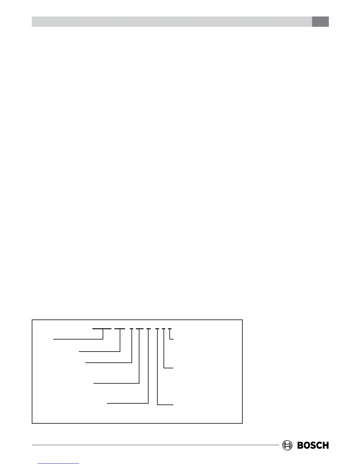
MODEL NOMENCLATURE
Table of Contents CP/BP Series 3
SUPPLY AIR LOCATION:
T - TOP (VT ONLY)
S - STRAIGHT THRU (HZ ONLY)
E - END BLOW (HZ ONLY)
RETURN AIR LOCATION:
L - LEFT
R - RIGHT
WATER CONNECTION LOCATION
F - FRONT
SERIES:
CP/BP
NOMINAL CAPACITY:
MBTUH
VOLTAGE DESIGNATION:
1- 208-230/1/60
CABINET CONFIGURATION:
VT - VERTICAL
HZ - HORIZONTAL
WATER TO REFRIGERANT HEAT EX:
C - COPPER
N - CUPRO-NICKEL
CP/BP 048 - 1 VT C - F L T