16 | Heat Recovery Package CE Series Heat Pump
CE Series Heat Pump6 720 220 048 (2014/08) Subject to change without prior notice
HEAT RECOVERY PACKAGE
The Heat Recovery Package (HRP) is a factory
mounted option. It consists of a forced pumped
unit that employs a circulating pump to move
water through a double wall/vented heat
exchanger and returns the heated water to the
water tank. The water is heated by superheated
refrigerant discharge gas from the compressor.
This waste heat of the cooling mode captured by
the heat recovery increases the capacity and
efficiency of the heat pump unit. If the air
temperature is uncomfortable coming from the
vents in the heating mode the heat recovery may
need to be turned off. In the heating mode, the
heat recovery captures heat that would normally
be used for space heating.
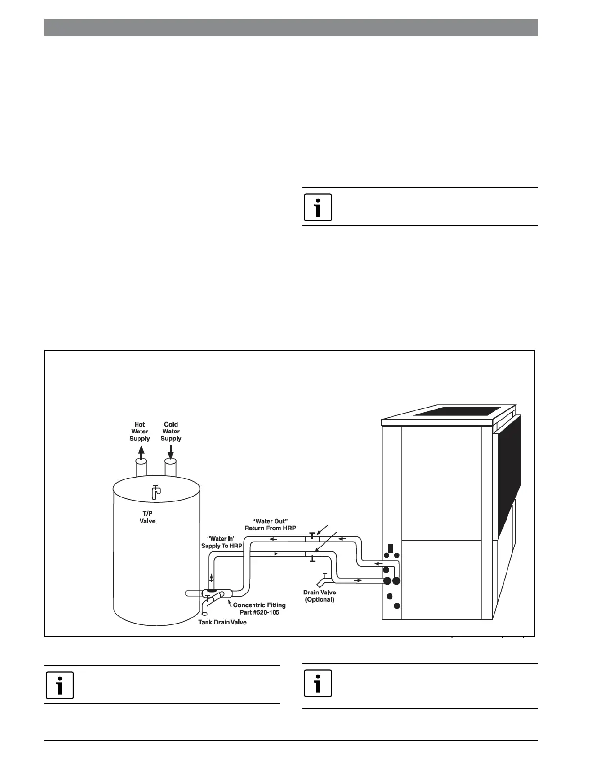
Typical Connection Piping (HRP)
Water Tank Preparation:
1. Turn off electrical or fuel supply to the water
heater.
2. Attach garden hose to water tank drain
connection and run other end of hose out
doors or to an open drain.
3. Close cold water inlet valve to water heater
tank.
4. Drain tank by opening drain valve on the
bottom of the tank, then open pressure relief
valve or hot water faucet.
5. Once drained the tank should be flushed with
cold water until the water leaving the drain
hose is clear and free of sediment.
6. Close all valves and remove the drain hose.
7. Install HR water piping.
HR Water Piping
All hot water piping should be a minimum of 3/8t
O.D. copper tube to a maximum distance of fifteen
(15) feet. For distances beyond fifteen feet but not
exceeding sixty (60) feet use 1/2” copper tube.
Separately insulate all exposed surface of both
connecting water lines with 3/8” wall closed cell
insulation. Install isolation valves on supply and
return to the heat recovery. (Figure #17)
Figure # 17
Concentric water fitting (p/n 520-105) is
recommended.
NOTE: Diagram for illustration purposes only.
Isolation
Valves
NOTE: Diagram is for illustration purposes only.
Ensure access to heat Pump is not restricted.
NOTE: All piping from HRP to domestic water
tank must be copper or any metal of stronger
alloy.

 Loading...


