Installation
15
Compress 3000 AWES – 6720892204 (2020/06)
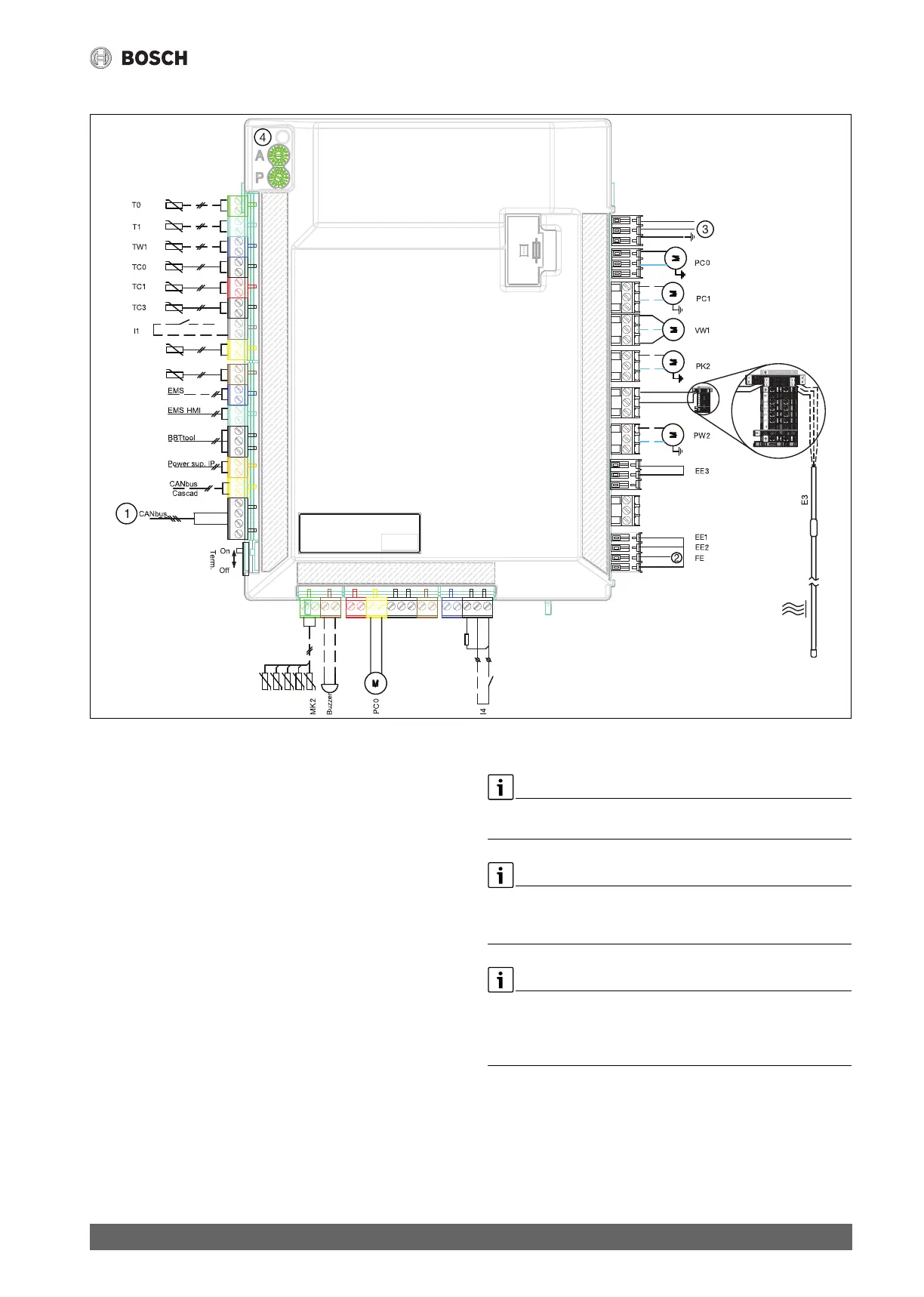
5.7.8 Connections of SEC 20 installer module of indoor unit with electric heater
Fig. 12 SEC 20 installer module of indoor unit with electric heater
Continuous line = connection made at the factory
Dotted line = connection made during installation:
[1] CAN-BUS to outdoor unit
[2] Alarm electric heater/pressure switch (~230 V input voltage)
[3] Power supply 230 V ~1 N
[4] Code switch and LED bus communication
[T0] Flow temperature sensor
[T1] Outside temperature sensor
[TW1] DHW sensor
[TC0] Heat transfer medium in
[TC1] Heat transfer medium out
[TC3] Condenser temperature
[I1] Ex. input
[TR7] Hot gas temperature sensor
[TR3] Liquid temperature sensor
[MK2] Condensation point sensors
[Buzzer] Alarm sounder (accessory)
[PC0] Pump primary circuit PWM signal
[I4] Ex. input
[EE2] Electric heater, step 2
[EE1] Electric heater, step 1
[EE3] Electric heater, step 3
[PW2] DHW circulation pump
[E3] Heating cable (HC), accessory (~230 V output)
[PK2] Heating pump cooling buffer/fan convectors
[VW1] 3-way diverter valve for DHW (accessory)
[PC1] Heating pump (heating system)
[PC0] Heating pump (brine pump)
Max load for relay outputs PW2, PK2, VW1, PC1: 2 A, cos φ > 0.4.
Maximum load for CUHP inst.: 6.3 A
Note regarding input I1 (connection 13, 14) and I4 (connection 49, 50).
Contact on the component or relay that is connected to this input must
be suitable for 5 V and 1 mA.
Note regarding [4]:
Coding switches A and P must not be adjusted! Otherwise malfunctions
and faults will occur.
Important: check the coding when a replacement part is used.

 Loading...


