6 720 820 872 (2016/12)CR 400 | CW 400 | CW 800
Product information | 7
2.5 Specifications
Fig. 3 Dimensions in mm
2.6 Product data on energy consumption
The product data on energy consumption can be found in the
operating instructions for the user.
2.7 Temperature sensor characteristics
When measuring temperature sensors, observe the following
requirements:
• Isolate the system before measuring.
• Measure the resistance at the cable ends.
• The resistance values represent average values and are
subject to tolerances.
2.8 Additional accessories
For precise information regarding suitable accessories, refer to
the catalogue.
Function modules and user interfaces of the control system
EMS 2:
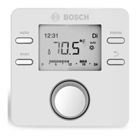
• User interface CR 10 as simple remote control
• User interface CR 100 as comfortable remote control
• MC 400: module for a cascade of several heat sources
• MM 100: module for one heating circuit with mixer,
cylinder charging circuit or constant heating circuit
• MM 200: module for 2 heating circuits with mixer, cylinder
charging circuits or constant heating circuits
• MS 100: module for solar DHW heating
6 720 812 361-02.2O
auto
man
fav
menu
info
123
25
32
101
Scope of delivery Æ Chapter 2.4, page 6
Measurements 123 × 101 × 25 mm
(Æ Fig. 3)
Rated voltage 10 ... 24 V DC
Rated power (excluding
illumination)
9 mA
BUS interface EMS 2
Control range 5 °C ... 30 °C
Permitted ambient temp. 0 °C ... 50 °C
Protection class III
Protection
• For wall-mounted installation
• In case of installation in the
heat source
• IP20
• IPX2D
Table 2 Specifications
°C : °C : °C : °C :
– 20 2392 – 8 1562 4 984 16 616
– 16 2088 – 4 1342 8 842 20 528
– 12 1811 r0 1149 12 720 24 454
Table 3 Resistance values for outside temperature sensors
°C : °C : °C : °C :
8 25065 32 9043 56 3723 80 1704
14 19170 38 7174 62 3032 86 1421
20 14772 44 5730 68 2488 – –
26 11500 50 4608 74 2053 – –
Table 4 Resistance values for flow and DHW temperature
sensors

 Loading...

