Do you have a question about the Bosch D8125INV and is the answer not in the manual?
Details FCC Class B digital device compliance and measures to correct interference.
Lists other documentation referenced in the manual for ordering purposes.
Explains specific type styles like bold, italic, and courier text used for clarity.
Details how tips, important notes, cautions, and warnings are presented for reader awareness.
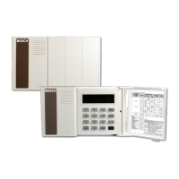
Lists key features of the D8125INV, including compatibility, user interface, and transmitter capacity.
Details technical specifications like user interface, operating voltage, current, and dimensions.
Explains how to expand system points using multiple D8125INVs and Inovonics transmitters.
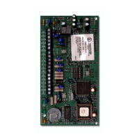
Illustrates and labels the back view of the D8125INV, showing connection points.
Provides step-by-step instructions for physically mounting the D8125INV unit.
Details the wiring process connecting the D8125INV to the control panel and FA400 receiver.
Outlines recommended initial programming steps for a new D8125INV installation.
Recommends labeling Inovonics transmitters with point numbers before programming.
Describes the initial display sequence and states upon powering up the D8125INV for the first time.
Explains displays for normal RF system status and 'Call for Service' conditions.
Provides the default passcode and instructions for entering it to access D8125INV functions.
Outlines the initial steps required to access menus for managing RF transmitters.
Guides on how to change the installer passcode for enhanced security.
Explains how to set a unique 3-digit System ID for the D8125INV, essential for multi-module systems.
Details the process of clearing the EEPROM to reset the module to factory defaults.
Allows setting the interval for supervising RF transmitter check-ins before reporting a 'Missing' condition.
Enables troubleshooting of individual RF transmitters by checking their status and signal strength.
Explains how the D8125INV supervises the FA400 receiver and the consequences of a loss of supervision.
Lists common reasons for transmitters going missing, such as dead batteries or damage.
Provides guidance on replacing low transmitter batteries and testing the transmitter.
Describes the operation of the D8125INV when powered down and then back up.
Presents common questions and answers regarding Inovonics wireless transmitters and systems.
Indicates the default installer passcode for initial setup.
Placeholder for the System ID used for transmitter and module identification.
Indicates the default RF system supervision interval.
| Model | D8125INV |
|---|---|
| Category | Network Hardware |
| Video Output | HDMI, VGA |
| Video Compression | H.264 |
| Resolution | Up to 1080p |
| Network Interface | 1 x 10/100/1000 Mbps Ethernet |
| Power Supply | 100 to 240 VAC |
| Operating Temperature | +0 °C to +40 °C (+32 °F to +104 °F) |