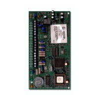
D9210B
Installation
D9210B Operation and Installation Guide
32206G Page 14 © 2002 Bosch Security Systems
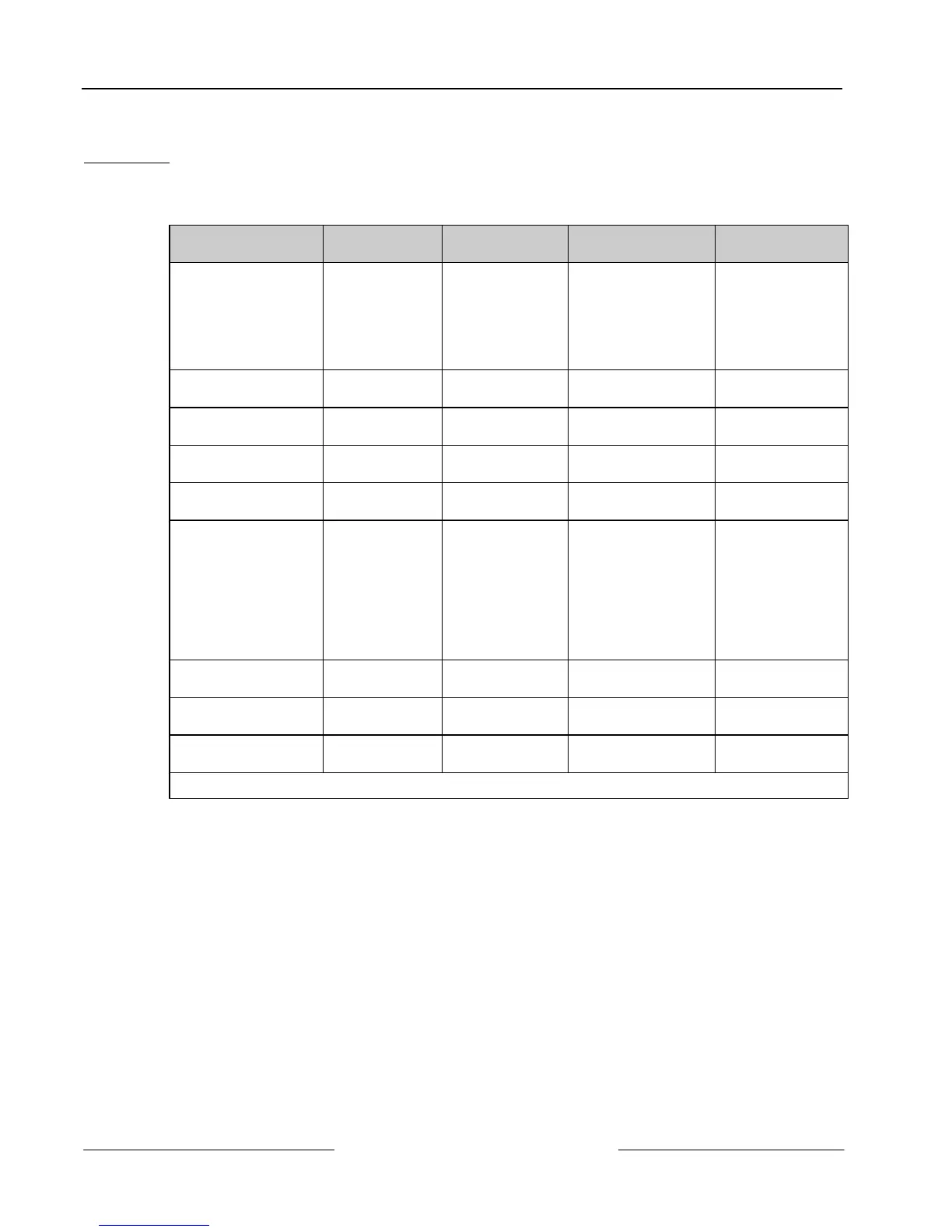
3.2.2 Pulling and Marking the Wires
Running wire. Use Table 4 to estimate the wire bundle size for your knockouts and where to mount the D9210B. Tag
your wire runs to prevent confusion during installation and troubleshooting. Figure 2 shows the wiring for a typical
D9210B installation.
Purpose
Suggested
Wire Tag
Approximate
Diameter
Recommended Wire
Type
Recommended
Color Code
Power/SDI data Tag A
0.25 in.
(6.4 mm)
4/22 AWG quad
(2500 ft. / 762 m)
4/18 AWG quad
(5000 ft. / 1,524 m)
SDI: A
(Green)
B
(Yellow)
Pwr: + (Red)
- (Black)
RTE power/input* Tag B 0.25 in.
(6.4 mm)
4/22 AWG quad Green/Black
REX power/input* Tag C 0.25 in.
(6.4 mm)
4/22 AWG quad Yellow/Black
Strike power* Tag D
0.375 in.
(9.5 mm)
2/16-18 AWG zip Red
Door contact* Tag E 0.125 in.
(3.2 mm)
2/22 AWG
(500 feet / 152 m)
White
Reader* Tag F 0.375 in.
(9.5 mm)
6/22 AWG
conductor
(500 feet / 152 m)
12 VDC: Red
5 VDC: Orange
COM: Black
D1: White
D0: Green
LED: Brown
Buzzer: Yellow
Buzzer* Tag G 0.125 in.
(3.2 mm)
2/22 AWG twist +(Red), - (Blk)
Emergency Exit* Tag I
0.125 in.
(3.2 mm)
2/18 AWG twist Blue
Power Supply
Transformer
Tag J 0.25 in.
(6.4 mm)
2/18 AWG zip Brown
* Be sure to multiply the wires by the number of D9210Bs in the enclosure.
Table 4: Typical Wire Planning Chart for the D9210B