50 en | Connecting the E2700 controller-drive tray to the drive trays DSA E-Series (E2700)
2015.10 | V2 | DOC Installation manual Bosch Sicherheitssysteme GmbH
9.3 Things to know – drive trays
Observe the following:
– Each DE6600 drive tray can contain a maximum of sixty 8.89-cm (3.5-in.).
– Each ESM in the or the DE6600 drive tray contains a pair of SAS In connectors and one
SAS Expansion (Out) connector.
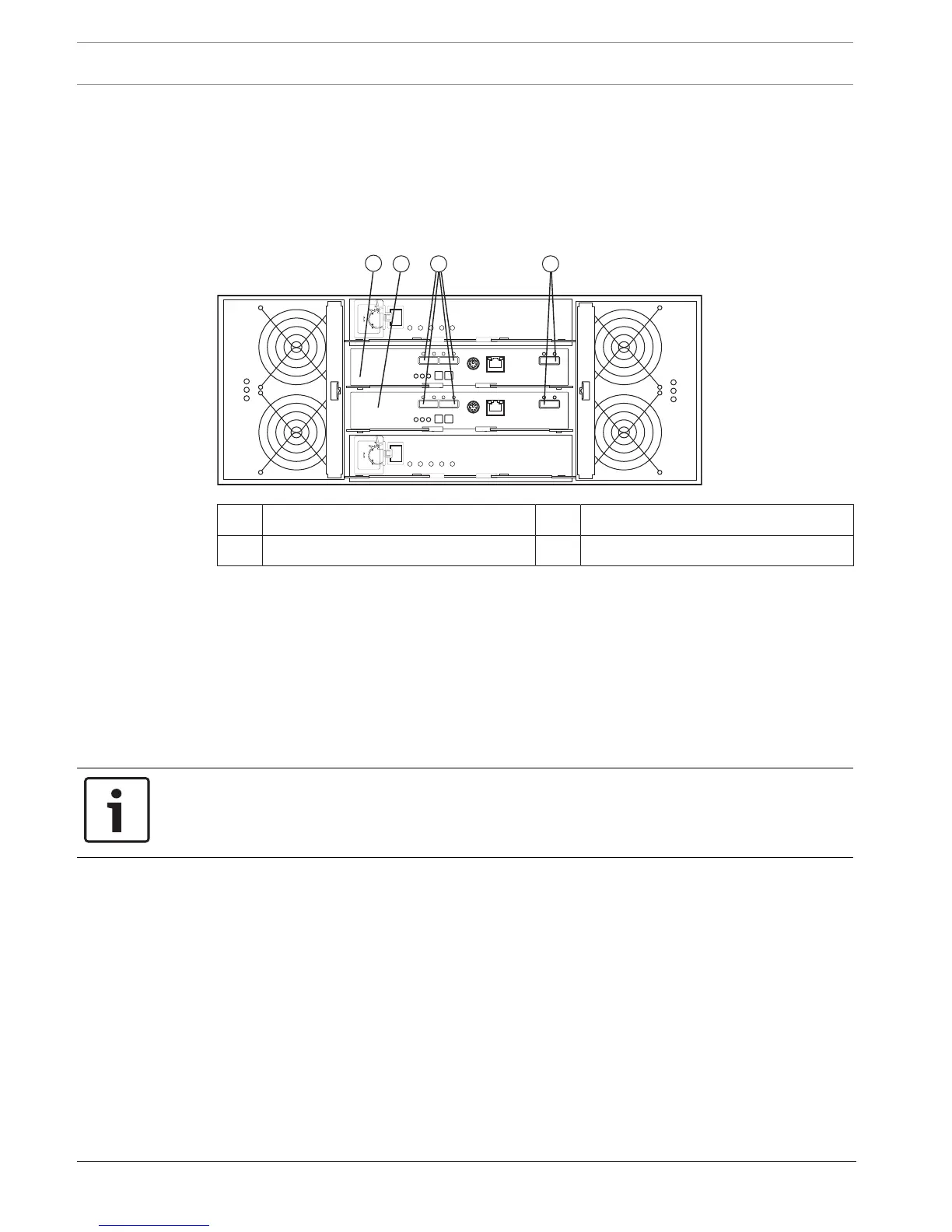
DE6600 drive tray – rear view
1 ESM A 3 SAS IN connectors
2 ESM B 4 SAS Expansion (out) connectors
9.4 Things to know – drive tray cabling configurations for the
E2712 controller-drive tray
The figures in this section show representative cabling configurations. The configurations
shown guarantee that redundant data paths exist between the controller-drive tray and all
attached drive trays in a storage array. You can attach the E2712 controller-drive tray to the
following drive trays: DE1600 drive trays or DE6600 drive trays.
You need two or four SAS cables to attach one or two drive trays to the controller-drive tray.
For each additional drive tray, you need two more SAS cables.
Notice!
To connect a drive tray to a controller drive tray, you need two Mini-SAS HD to Mini-SAS
cables.
To connect an additional drive tray to a drive tray, you need two Mini-SAS to Mini-SAS cables.
These general rules apply:
– All cables connect a SAS Expansion (Out) port at one end to a SAS IN port at the other
end. Never connect a SAS Expansion (Out) port to another SAS Expansion (Out) port.
Never connect a SAS In port to another SAS IN port.
– You can use either of the two SAS IN ports on an ESM for a connection, but it is best
to follow the conventions described in the documentation so your storage
management software represents the storage array consistently.
– The drive trays in the chain of connections from controller A are in the reverse order from
those whose connections start from controller B. That is, the last drive tray in the chain
from controller A must be the first drive tray in the chain from controller B.