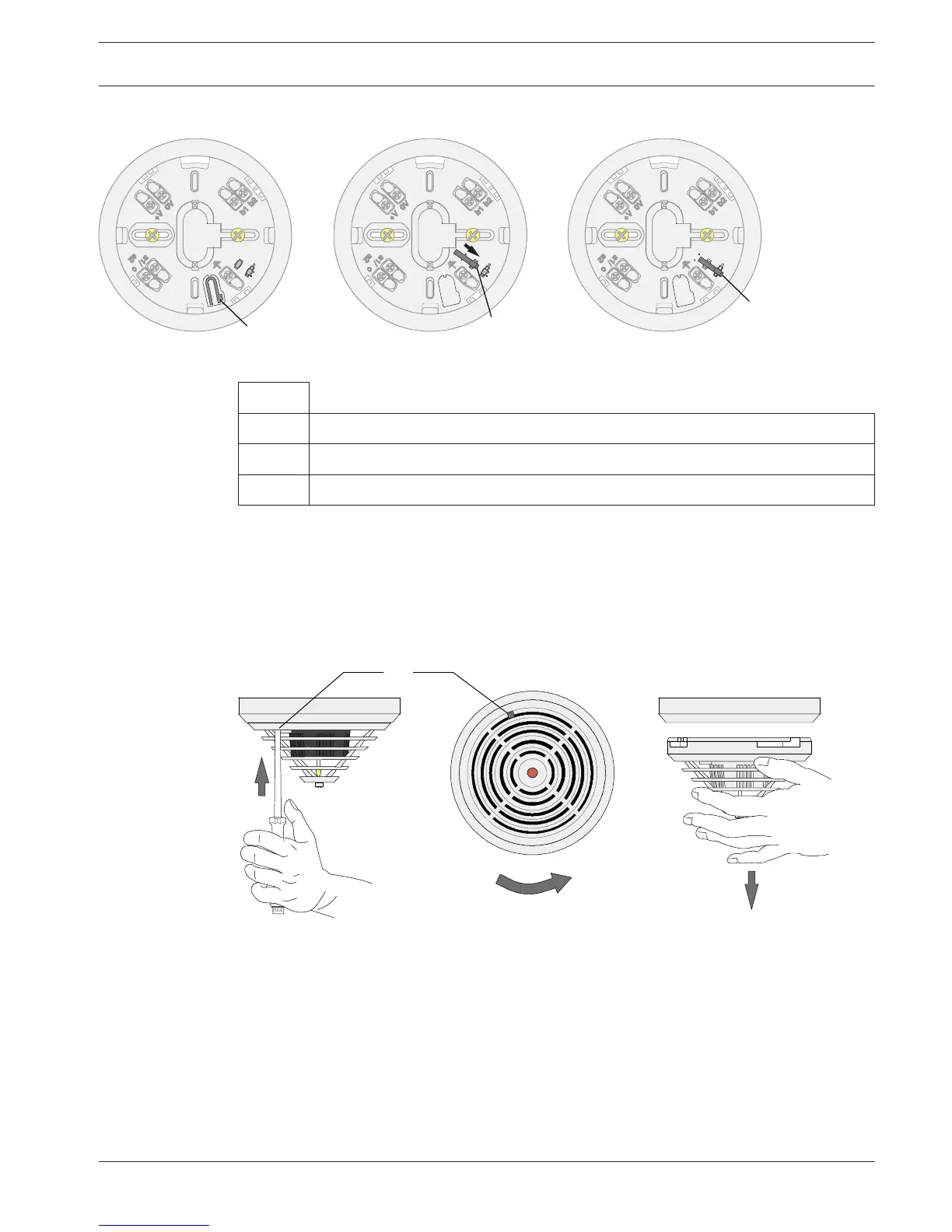
Figure 5.1: Activation of the removal protection mechanism
Key
1 Bolt (X) before breaking out
2 Bolt (X) fitted, but deactivated
3 Locking activated
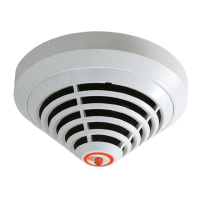
Detector Removal
Unlocked detector heads are disassembled by turning them to the left and removing them
from the base.
Locked detector heads are disassembled by inserting a screwdriver into the unlocking opening
(Y) so that the bolt is pushed upward; at the same time, the detector head should be turned
to the left (see , page 23).
Figure 5.2: Detector removal (locked detector module)
Addressing
There are three rotary switches on the bottom of the detector; these are used to select
automatic or manual address allocation with or without auto-detection.
The following settings are possible:
5.6
5.7
Automatic Fire Detectors LSN
improved
Connection | en 23
Bosch Sicherheitssysteme GmbH Operation Guide 12/2012 | 8.1 | F.01U.003.448