5. Place the cap on the base plate in such a way that the two hooks (item A) are inserted
into the slits. Press the cap lightly onto the base plate until the snap-fit hook (item C)
engages.
Technical data
Operating voltage 5–30 V DC
Weight 45 g
Display medium 2 LEDs
Permissible wire gauge 0.6–2 mm
Maximum current consumption 20 mA
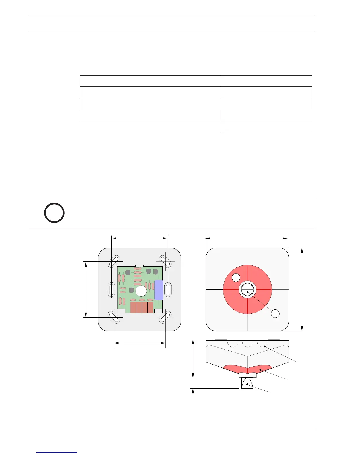
MPA External Detector Alarm Display
Installation note
– Fitted directly to the wall or ceiling.
– To feed cables through for surface mounting, punch out the prepared entry points (see
Installation note, page 28, item X) on the housing.
– For flush-mounted cable insertion, feed the cable through the opening beneath the
connection board.
Figure 6.1: Installation of the MPA External Detector Alarm Display
Connection
The MPA is connected via four Wago terminals.
6.7.2
28 en | Accessories
Automatic Fire Detectors LSN
improved
12/2012 | 8.1 | F.01U.003.448 Operation Guide Bosch Sicherheitssysteme GmbH