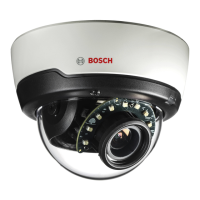
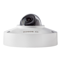
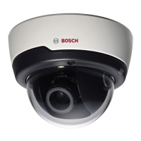
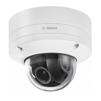
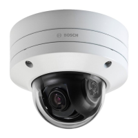
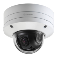
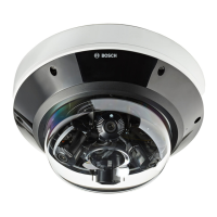
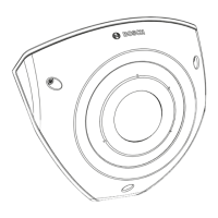
FLEXIDOME IP 3000i IR | FLEXIDOME IP micro
3000i | DINION IP 3000i IR | FLEXIDOME IP turret
3000i IR
Configuration | en 23
Bosch Security Systems B.V. User manual 2020-01 | V02 | DOC
The focal length is determined by the lens. The shorter the focal length, the wider the field of
view. The longer the focal length, the narrower the field of view and the higher the
magnification.
Show sensor values...
Click to automatically see the camera parameters, for example, Tilt angle [°], Roll angle [°]
and Focal length [mm]. These calibration values are measured by the device sensors. Click OK
to transfer them to the Positioning settings page.
Sketch
Click to improve the automatic calibration. The Sketch Calibration window is displayed.
The Sketch functionality offers an additional, half-automatic calibration method. This
calibration method allows you to describe the perspective in the camera’s field of view by
drawing vertical lines, ground lines, and ground angles in the camera image and entering the
correct size and angle. Use the Sketch functionality if the result of the automatic calibration is
not sufficient.
You can also combine this manual calibration with the values for roll angle, tilt angle, height
and focal length calculated by the camera or entered manually.
Select the Calculate check box to obtain the roll angle, tilt angle, height and focal length from
the sketched calibration elements - vertical lines, ground lines and angles - you have placed in
the camera.
Clear the Calculate check box to enter a value manually or to refresh to the values provided by
the camera itself.
Calibrating cameras using the Sketch Calibration window
To determine non-automatically set values:
1. Enter the value for tilt angle, roll angle, height and focal length if the value is known, for
example, by measuring the height of the camera above the ground, or reading the focal
length from the lens.
2. For each value that is still unknown, select the Calculate check box, then place a
calibration element on the camera image. Use these calibration elements to trace
individual outlines of the displayed environment in the camera image and define the
position and size of these lines and angles.
– Click to place a vertical line across the image.
A vertical line corresponds to a line that is perpendicular to the ground plane, such
as a door frame, edge of a building or a lamp post.
– Click to place a line across the ground in the image.
A line on ground corresponds to a line that is on the ground plane, such as a road
marking.
– Click to place an angle on the ground in the image.
The angle on ground represents an angle lying on the horizontal ground plane, such
as the corner of a carpet or parking bay markings.
3. Adjust the calibration elements to the situation:
– Enter the real size of a line or angle. To do this, select the line or angle, then enter
the size in the corresponding box.
Example: You have placed a line on ground across the lower side of an automobile.
You know that the automobile is 4m long. Enter 4m as the length of the line.
– Adjust the position or length of a line or angle. To do this, drag the line or angle or
move the end points to the desired position in the camera image.

 Loading...