Do you have a question about the Bosch FWA 44 Series and is the answer not in the manual?
Details measurement limits and precision for various parameters.
Shows pin assignments for the PC's back panel connectors.
Explains the hardware license key and its function.
Describes how the dongle connects to the PC.
Illustrates the physical cable connections within the system.
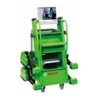
Shows the system layout for radio communication.
Shows the schematic of the cable splitter box.
Details pin configurations for the KP.
Describes the physical components and tasks of the splitter box.
Details the connector pin assignments for the splitter board.
Shows the schematic diagram of the mess box.
Describes the power supply board's tasks and function.
Explains how to adjust potentiometers for calibration.
Lists the primary functions of the measurement box.
Details pin assignments for charging connections.
Describes the 433 MHz radio module, its tasks, and power.
Describes the 2.4 GHz radio module, its tasks, and power.
Shows radio and cable versions of the measuring element.
Explains battery charging electronics operation.
Shows the functional diagram of the measuring element.
Lists technical specifications and features of the CCD camera.
Explains achieving accuracy via mechanical/electronic adjustment.
Describes the CCD camera's core function and resolution.
Guides on verifying and setting battery charging voltage.
Details software setting and updates for Flash-EPROM.
Guides on reading and reflecting adjustment values from camera.
Guides on reading and reflecting adjustment values.
Explains the measuring principle of the CCD camera.
Details the process for changing the camera and zero point adjustment.
Provides instructions for changing the measuring processor.
General guidelines for operating multiple axial cutter devices.
| Brand | Bosch |
|---|---|
| Model | FWA 44 Series |
| Category | Power Tool |
| Language | English |