Do you have a question about the Bosch FWA 43 Series and is the answer not in the manual?
Groups Danger!, Warning!, Caution!, and Important symbols indicating hazards to the user.
Groups Info, Single-step procedure, Intermediate result, and Final result symbols used in procedures.
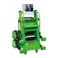
Provides a functional overview of the FWA 43xx / FWA 44xx chassis measuring system.
Lists the components included in the scope of delivery for the FWA system.
Details the metering ranges and measurement accuracies for various wheel alignment parameters.
Specifies the frequency range of the radio system for the measuring elements.
Provides technical specifications for the PC-Computer unit used with the FWA system.
Details the pin assignment for the back side of the PC, including various ports.
The hardware license number is stored in the dongle, managing software licenses and connected to LPT 1. It details function, connection, license number, and licensing procedures.
Illustrates the functional diagram showing cable connections for the system components.
Illustrates the functional diagram showing radio connections for the system components.
Lists the primary tasks of the communication processor, including control and data transfer.
Explains the role of the communication processor as a central manager for measuring functions.
Details the pin assignment for the communication processor board.
Provides the functional diagram of the cable splitter box.
Describes the splitter box element, its tasks (serial data transfer, fuse protection, partitioning of data/power) and function (dividing serial connection and power supply).
Details the connector pin assignment and function of the splitter board.
Details the measurement box element, its tasks (data transfer, supply voltage, protection) and function.
Provides the functional diagram of the mess box, illustrating its internal connections and components.
Explains the mess box function, providing necessary low-voltages and acting as a data manager.
Describes the power supply board's function in generating voltages for the fan and communication processor.
Shows the mess box installed within the measurement device.
Shows the splitter box installed within the measurement device.
Illustrates the fan component of the mess box.
Details the power supply board's tasks and functional description, transforming voltage and providing power.
Explains potentiometer settings for Vadj (R8) and Tadj (R16) for voltage adjustment and fan control.
Provides an overview of different receptacles for the MWA, referring to the spare parts list.
Details the connector pin assignment for charging equipment.
Details the radio module, its tasks, function, and power supply for 433 MHz operation.
Details the radio module, its tasks, function, and power supply for 2.4 GHz operation.
Provides an overview of the measuring element, including its radio and cable versions and charging.
Describes the conductor board charging electronics, its function, and how to verify and set charging voltage.
Provides technical data for the Nickel Cadmium battery used in the radio version.
Details the measuring processor's tasks, functional diagram, DIP switch settings, board layout, EPROM, adjustment values, and processor changes.
Describes the CCD camera, its function, measuring principle, opening angle, and technical data.
Lists the technical data and features of the CCD camera system.
Explains how to achieve measuring accuracy through mechanical and electronic adjustment of the camera.
Details the process of reading and reflecting adjustment values between the measuring processor and camera.
Outlines the procedure for changing the camera and performing a zero point adjustment.
Covers keyboard functions for radio and cable operations, including channel change, LED displays, and button operations.
Covers general instructions, radio frequency, software updates, and channel management for axial cutter devices.
Details the PC-splitter box cable and its connections.
Describes the power supply cable for +8 V DC.
Details the cable for the power supply of the fan.
Describes the serial cable connecting PC to Communication Processor (KP).
Details the line filter for the power supply board.
Describes the cable connecting the Communication Processor (KP) to the splitter board.
Details the cable connecting the radio module to the splitter board.
Describes the splitter board connection to a fitting socket.
Describes the measuring processor connection to a fitting socket.
Details the splitter board connection to a charging socket.
Describes the fitting socket connection to the splitter board for storage.
Details the splitter board connection for +8.00 V DC.
Describes the key measuring processor board.
Details the measuring processor connection to a fitting socket with a turn-tilt board.
Describes the charging electronic connection to the measuring processor.
Details the measuring processor connection to fitting sockets.
Describes the 6.5 m measuring element connection cable.
Describes the 4.5 m measuring element connection cable.
Details the measuring processor CCD camera connection.
Describes the charging cable for the measuring element.
Illustrates cabling diagrams for connecting the measuring element.
Details the installation of Windows XP Professional Multi-Language for the FWA system.
Explains the process of recovering the system using the Recovery DVD.
Provides instructions for installing software packages onto the FWA system.
Provides steps for uninstalling FWA programs and software components.
Covers maintenance functions including version reports, equipment status, and runtime logs.
Explains direct angle measurement, track, camber, and angle spread values, and transmitter power.
Details the adjustment program for track, camber, and level adjustments, including when adjustments are necessary.
Explains how to save user individual data, including customer data, measuring protocols, and vehicle data.
Covers the Flash Writer function, operating instructions, preparation, and equipment/version checks for firmware updates.
Details the version check process that occurs after firmware update execution.
Outlines the steps for updating the communication processor and the conditions for execution.
Explains the process for updating measuring processors, including sequential updates and conditions for execution.
Provides special handling instructions for individual measuring processors during updates, including connection and skipping steps.
Details the process for updating cameras, including sequential updates for front and rear cameras.
Describes settings for language, version comparison, and using other firmware files within Flash Writer.
Mentions that error pages are displayed with corresponding messages.
Covers additional information for older version installations, individual case handling, and system monitor functions.
Explains the system monitor's function for reading equipment data and its provided tabs.
Describes the main operating elements of the program, summarized in a panel.
Explains the register card displaying type and version information of selected equipment with color coding.
Lists functions available via "Actions", such as Reconnect, Reset Unit, and Clear data fields.
Explains the significance of fields in display blocks for CCD line and transmitter-LED parameters.
Details the "Graph" tab, allowing camera selection, display resolution, and signal response visualization.
Lists further functions available via "Actions", including reading toe and camber pictures.
Explains the Camera Recovery Tool's function for saving and recovering camera data, including backup and recovery procedures.
Describes the user software, its modular structure, and the main program/user interface.
Details the CCD server's role, tasks, function, path/program files, and program start.
Covers CCD server configuration settings, calculation of measured values, and program functions.
Discusses CCD server device details, settings, channel management, and sensor channel settings.
Explains CCD server command input, sensor values, and overviews of important commands.
Describes the Demo server's role, tasks, function, path/program files, and program start.
Details the License server's role, tasks, function, path/program files, and program start.
Covers license server status, properties, context menu, and program execution.
Details the ILSV server's role, tasks, function, path/program files, and program start.
Describes the Target-Data-Editor's function, path/program files, program start, and file descriptions.
Explains the Remote ControlEx software's function, task, path/program files, and program start.
Details the instruction report for wheel alignment devices based on Windows technology, covering checks and user training.
| Brand | Bosch |
|---|---|
| Model | FWA 43 Series |
| Category | Power Tool |
| Language | English |