|
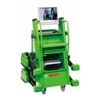
2 | FWA 43xx / FWA 44xx |
1 690 326 006 2008-8-25 Robert Bosch GmbH
en
Table of contents English
1. Symbols Used 4
2. Devices description 5
2.1 Functional description FWA 43xx / FWA 44xx 5
2.2 Scope of delivery 5
3. Technical data 6
3.1 Metering range and measuring accuracies 6
3.2 Frequency range 6
3.3 Weights and measurements 6
3.4 Temperature and working environment 6
3.5 Power supply 6
3.6 PC-Computer unit 6
4. PC-Computer unit 7
4.1 Connections 7
4.2 Dongle 8
4.2.1 Function 8
4.2.2 Connection 8
4.2.3 License number 8
4.2.4 Licensing 8
5. Functional diagram 9
5.1 Cable format 9
5.2 Radio format 10
6. Communication processor 11
6.1 Tasks 11
6.2 Function 11
6.3 Pin assignment 11
6.4 Functional diagram of cable splitter box 12
7. Splitter box (Cable) 13
7.1 Element 13
7.1.1 Tasks 13
7.1.2 Function 13
7.2 Splitter board 14
7.2.1 Connector pin assignment 14
7.2.2 Function 14
8. Measurement box (Radio) 14
8.1 Element 14
8.1.1 Tasks 14
8.1.2 Functional diagram of mess box 15
8.1.3 Function 16
8.1.4 Power supply board 16
8.2 Mess box in the device 17
8.3 Splitter box in the device 17
8.4 Fan mess box 17
8.5 Power supply board 17
8.6 Potentiometer- Setting 18
9. Charging equipment MWA 20
9.1 Overview sensor 20
9.2 Connector pin assignment 20
10. Radio box 21
10.1 Radio module 433 MHz (green) 21
10.2 Radio module 2.4 GHz (blue) 21
11. Measuring element 22
11.1 Over view of measuring element 22
11.2 Conductor board charging electronics 23
11.2.1 Function 23
11.2.2 Verify and set charging voltage 23
11.3 Battery: For radio version 24
11.4 Measuring processor 24
11.4.1 Tasks 24
11.4.2 Functional diagram MWA 25
11.4.3 DIP- switch 26
11.4.4 Board layout according to functionali–
ties 26
11.4.5 Flash- EPROM 26
11.4.6 Reading/ reflecting the adjustment
values 26
11.4.7 Change measuring processor 26
11.5 CCD camera 27
11.5.1 Functional diagram 27
11.5.2 Function 27
11.5.3 Measuring principle 27
11.5.4 Opening angle: 27
11.5.5 Technical data / features 28
11.5.6 Adjustment value 29
11.5.7 Reading/ reflecting the adjustment
values: 29
11.5.8 Change camera 29
11.5.9 Keyboard radio 30
11.5.10 Function 30
11.5.11 Keyboard function 30
11.5.12 Keyboard board cable 30
11.5.13 Function 30
11.5.14 Keyboard function 30
12. Operation of several axial cutter device (Radio)
31
12.1 General instructions 31
12.1.1 Radio frequency 31
12.1.2 Flash- EPROM 31
12.2 Change in transmission channel of measuring
element 31
12.2.1 Using key combination MWA 31
12.2.2 Using software program CCD server 31
12.3 Change in transmission channel of mess box 31
 Loading...