20
Miter Detent System
MITER SCALE POINTER ADJUSTMENT
1. Rotate table to 0° detent position and lock in
place.
2. Raise the head assembly to the full UP position.
3
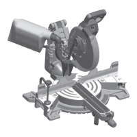
. Loosen the pointer adjust screw that holds the
miter scale pointer in place (see Fig. 12).
4. Position the pointer to align with the 0° line.
Tighten the screw.
Kerf Insert Adjustment
The kerf inserts should be adjusted close to the
blade, but without touching the blade, to avoid
tear-out on the bottom of the workpiece.
1. Hold the saw head assembly down and push in
the head assembly lock pin (item 36 – page 10)
to keep the saw in the DOWN position.
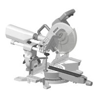
2. Loosen the four kerf screws using a 5mm Hex
key, (Fig. 13).
3. Adjust the kerf inserts as close to the blade
(teeth) as possible without touching the blade.
4. Tighten the kerf screws.
NOTE: At extreme bevel angles, the saw blade may
slightly cut into kerf insert.
Pointer Adjust
Screw
Miter Scale
Pointer
Fig. 12
Adjustments
Fig. 13
Kerf
Screws

 Loading...
