Water-To-Water Unit Controller | 24Greensource CDi Series TW Model
8733954853 (2020/04)Greensource CDi Series TW Model
Subject to change without prior notice
A 120-second time delay is built into the
low-pressure switch to avoid nuisance trips with
low-fluid temperatures. While in a soft-lockout
condition the display will show the specific fault
(for example LP1) and the “service” LED will turn
on according to the malfunction mode. If the
setting for malfunction mode is “steady,” the
service LED will turn and remain on. If the setting
is “pulse,” the service LED will blink according to
the blink code as follows:
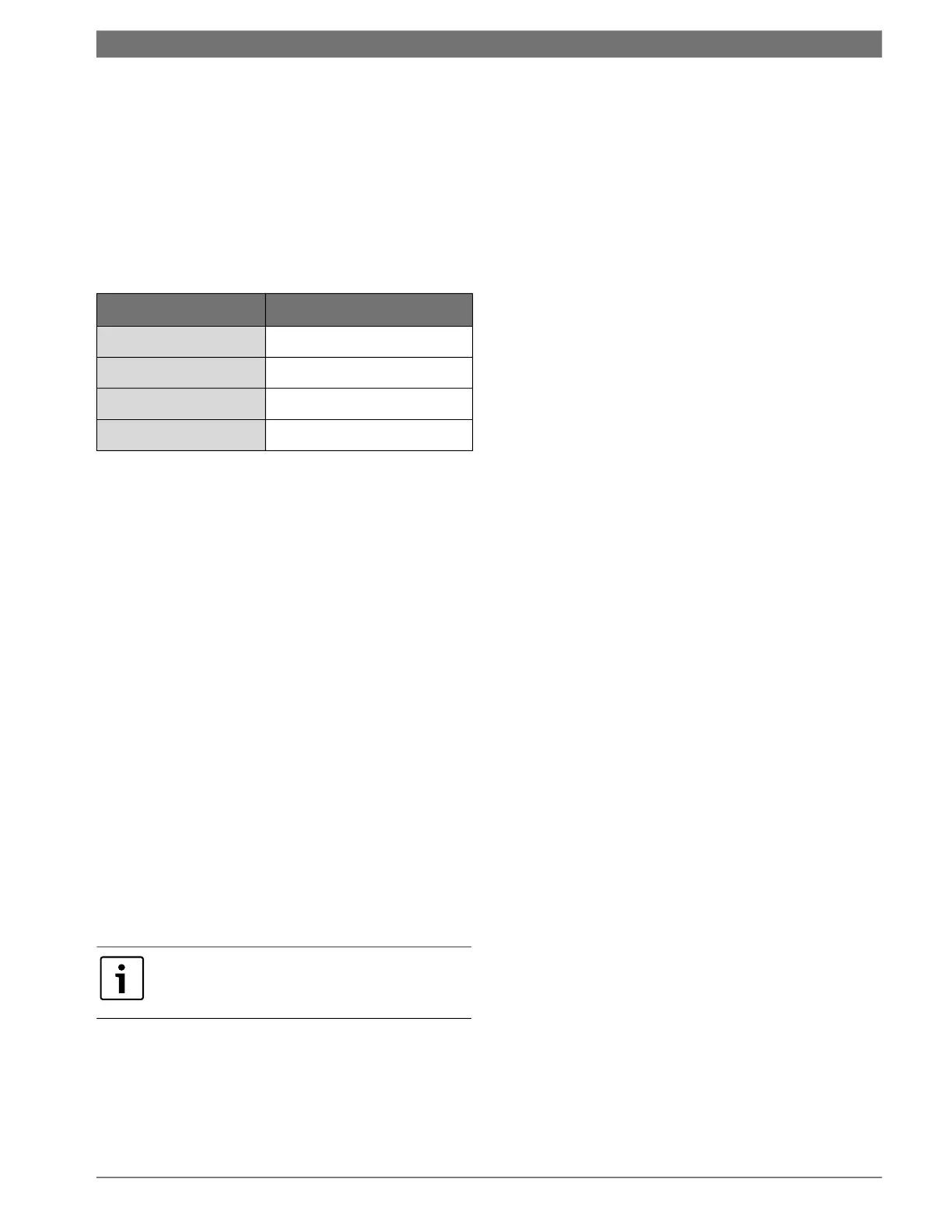
Table 5 Blink code
Brownout Protection
The control will disable all outputs if the supply
voltage drops below 17 VAC. The outputs will be
enabled if the supply voltage rises and remains
above 17 VAC for the five-minutes time delay.
During that time, the control will display “bro.”
Manual Lockout
The unit or refrigeration circuit will go into a
manual lockout if the HPS or LPS opens (LPS open
more than 120 seconds each time) twice within
one hour. During manual lockout the
compressor(s) is turned off and locked out and the
display will show the fault (for example LP1) and
the “service” LED “malfunction” output will either
be steady or blink according to the malfunction
mode as described above. If selection for
compressor is “Du” (see configuration) and one
compressor has locked out, the control will switch
the call to the other compressor. If compressor
setting is “Si,” the control shall not switch the call
to the other compressor.
Pump Cycling
When ordered with the optional pump relay, the
controller will cycle either the load, source, or both
pumps with the compressor operation. Please see
the wiring diagrams on page #35 through page #40.
Operating Instructions
Refer to Fig. 13 on page #22.
User Interface
The following parameters are displayed on the
screen:
• Control fluid temperature when in normal
mode
• Settings within the configuration mode
• Individual operating mode temperature set
points
• Fault display
UP Button
• Press once to display the current set-point
temperature.
• After the current set-point temperature is
displayed, pressing again will increment the
set point 1 degree for every push. Pressing and
holding the UP button increments the set point
at a rate of 4 degrees per second.
• When pressed with the DOWN arrow for 5
seconds, the control will display the current
temperature scale (Fahrenheit or Celsius).
• Used to change the settings for: temperature
scale, dead band, test mode, initial delay,
compressor, pump, and malfunction settings.
DOWN Button
• Press once to display the current set-point
temperature.
• After the current set-point temperature is
displayed, pressing again will decrement the
set point 1 degree for every push. Pressing and
holding the DOWN button will decrement the
set point at a rate of 4 degrees per second.
• When pressed with the UP arrow for 5
seconds, the control will display the current
temperature scale (Fahrenheit or Celsius).
• Used to change the settings for: temperature
scale, dead band, test mode, initial delay,
compressor, pump, and malfunction settings.
Blink Code Fault Condition
ONE BLINK
High-Pressure Circuit 1
TWO BLINKS
Low-Pressure Circuit 1
THREE BLINKS
High-Pressure Circuit 2
FOUR BLINKS
Low-Pressure Circuit 2
To reset a unit after a hard lockout, the user
needs to recycle power or switch the
controller to the OFF mode.