Installation 51/68
RE 15302-WA/05.2019, Hägglunds CB, Installation and maintenance manual , Bosch Rexroth Mellansel AB
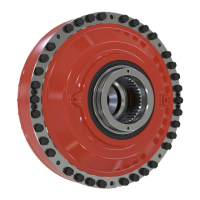
Fig. 47: Hydraulic connections
7.4.7 Hydraulic connections
When using (thick wall) piping and in applications with frequent reversal of rotation
direction, it is recommended to t exible hoses between the motor and piping to
avoid damage due to vibration and to simplify installation of the motor. The length of
the hoses should be kept as short as possible.
DD00087671
Table 18: Hydraulic connections
*SAE flange J 518 , code 62, 420 bar (6000 psi).
All connections are normally plugged at delivery.
Connection Description Dimensions Remarks
A1, A2 Main connection 1 1/4"and 1 1/2" *
If A is used as the inlet, the motor shaft rotates
counterclockwise, viewed from the motor shaft side.
C1, C2 Main connection 1 1/4" and 1 1/2" *
If C is used as the inlet, the motor shaft rotates clockwise,
viewed from the motor shaft side.
D1 Drain connection G 1 1/4"
D2, D4 Alternative drain connection G 1 1/4"
D3 Alternative drain connection G 1"
T1 Test connection M16 x 2
Used to measure pressure and/or temperature at the main
connections.
T2 Test connection M16 x 2 Used to measure pressure and/or temperature in motor casing.
T3 Test connection G 1/4" Used to measure pressure and/or temperature in motor casing.
T4A, T4C Pressure connection G 1/2" Connection for double ended torque arm.
F1, F2 Flushing connections G 1/4" For ushing of radial lip seal.
F3 Flushing connection G 1/2" For ushing of axial bearing and motor case.
Connection side of the motor Shaft side of the motor
DD00087674
 Loading...
