EasyManua.ls Logo

Bosch LV009 User Manual

Bosch LV009
64 pages
To Next Page IconTo Next Page
Page #1 background imageLoading...
Page #1 background image
Installation and Maintenance Manual
LV MODEL
8733944336 (2016/09)

Table of Contents

Questions and Answers:

Bosch LV009 Specifications

General IconGeneral
Model NumberLV009
Heating Capacity9, 000 BTU/h
Cooling Capacity9, 000 BTU/h
RefrigerantR410A
Operating Temperature (Heating)-13°F to 75°F
Power Supply208-230V, 1 Phase, 60 Hz
Indoor Unit Dimensions (H x W x D)8.3 inches
Outdoor Unit Dimensions (H x W x D)21.3"

Summary

Key Symbols and Safety Warnings

Warning Symbols and Definitions

Explains warning symbols and keywords indicating risk levels.

Critical Safety Precautions

Combines critical warnings for installation and operation safety.

Model Nomenclature Explanation

General Description and Handling

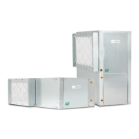
Unit Overview

Provides an overview of the LV series heat pump features and capabilities.

Installation Preparation

Site and Unit Checks

Outlines pre-installation checks for job site and unit condition.

Installation Site Selection and Checks

Site Preparation Requirements

Specifies site requirements like temperature, acoustics, and access.

Unit Inspection Checklist

Lists checks to perform before installing the unit.

Hanging Bracket Kit Installation

Safety Warnings for Hanging

Critical warnings regarding screw reuse, code compliance, and rod anchoring.

Duct System and Condensate Drain

Duct System Requirements

Details requirements for return air, supply air, and duct insulation.

Condensate Drain Installation

Details requirements for condensate drain line installation, pitching, and traps.

Piping Connections and Wiring

Water and Ground Loop Piping

Guidelines for piping in water and ground loop systems.

Field Power Supply Wiring

Details compliance with NEC, voltage matching, and wiring practices.

ECM-UPM Control and Safety Devices

UPM Board Controller Features

Describes the UPM board's role in compressor operation and safety monitoring.

UPM Board Safety Features and Functions

Freeze Sensor and Lockout Reset

Pre-Start-Up Checks and Operating Limits

System Checkout Procedures

Lists pre-startup checks for voltage, connections, and piping.

Scroll Compressor Rotation Check

Sequence of Operation (UPM)

ECM Control Board De-humidification Sequence

Unit Start-Up Procedures

Cooling Mode Start-Up

Steps for starting the unit in cooling mode and checking performance.

Heating Mode Start-Up

Steps for starting the unit in heating mode and checking performance.

Flow Regulation and Flushing

Application Considerations

System-Specific Application Guidelines

Geothermal Closed Loop Systems

Highlights the need for specialized design knowledge for closed loop systems.

Water Quality Considerations

Piping and Options

Additional Unit Options

ECM Fan Motor Options

Constant Airflow ECM Motor Features

Troubleshooting Overview

Unit Troubleshooting Guide

Table listing common problems, causes, and solutions.

Compressor Operation Issues

Troubleshooting steps for fan running but no compressor operation.

Troubleshooting Common Problems

No Compressor or Fan Operation

Troubleshooting steps for no compressor or fan operation.

Troubleshooting Fan Operation

PSC and ECM Fan Motor Issues

Troubleshooting for PSC and constant torque motor fan operation.

Troubleshooting Operational Issues

Airflow and Mode Shifting Problems

Troubleshooting for airflow, mode shifting, and abnormal supply air temps.

Troubleshooting Environmental and Noise Issues

Humidity, Noise, and Water Hammer

Troubleshooting for high humidity, noise levels, and water hammer.

Maintenance Schedule and Procedures

Decommissioning and Environmental Protection

Covers safe decommissioning, refrigerant recovery, and waste disposal.

Unit Check Out Sheet

Customer and Unit Data Recording

Sections for recording customer, unit nameplate, and operating condition data.

Related product manuals