Flexible Automation
Digital input modules
1-7
1070 072 144 -101
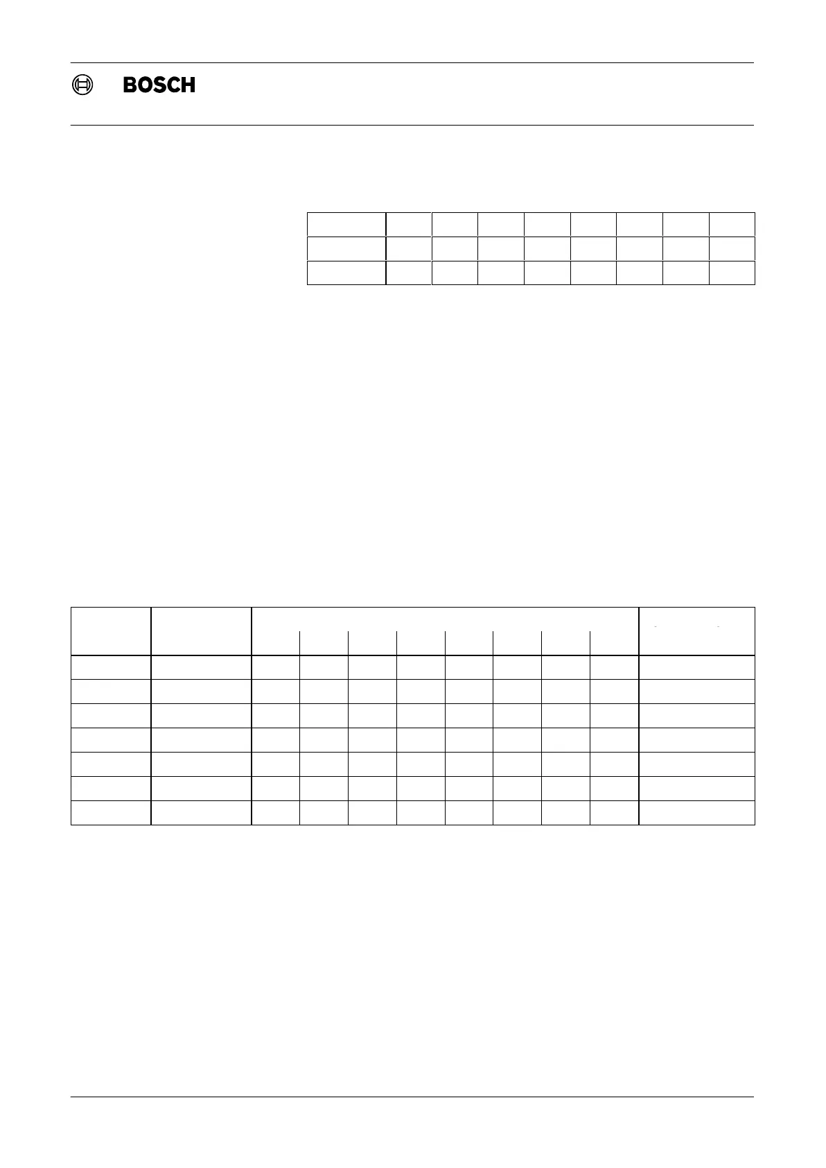
Switch
1 2 3 4 5 6 7 8
Bit value 2
0
2
1
2
2
2
3
2
4
2
5
2
6
2
7
Value 1 2 4 8 16 32 64 128
Fig. 1-7 Dip switch, value
. Switch 1 must always be OFF, as only even numbers are allowed for
start addresses.
The input modules occupy the following address ranges:
D Input module with 95 inputs occupies 12 bytes
D Input module with 32 inputs occupies 4 bytes
D Input module with 16 inputs occupies 2 bytes
To avoid gaps and double assignments, the start addresses should always
be allocated as follows:
D Input module with 95 inputs: 0, 12, 24, ...
D Input module with 32 inputs: 0, 4, 8, ...
D Input module with 16 inputs: 0, 2, 4, ...
The following table shows a sample assignment.
Module Start address
Dip switch setting
Bytes occupied
1 2 3 4 5 6 7 8
95 inputs 0 OFF OFF OFF OFF OFF OFF OFF OFF 0.0 to 11.7
32 inputs 12 OFF OFF ON ON OFF OFF OFF OFF 12.0 to 15.7
16 inputs 16 OFF OFF OFF OFF ON OFF OFF OFF 16.0 to 17.7
16 inputs 18 OFF ON OFF OFF ON OFF OFF OFF 18.0 to 19.7
32 inputs 20 OFF OFF ON OFF ON OFF OFF OFF 20.0 to 23.7
95 inputs 24 OFF OFF OFF ON ON OFF OFF OFF 24.0 to 35.7
16 inputs 36 OFF OFF ON OFF OFF ON OFF OFF 36.0 to 37.7
Fig. 1-8 Addressing, input module example