Flexible Automation
Digital output modules
2-7
1070 072 144 -101
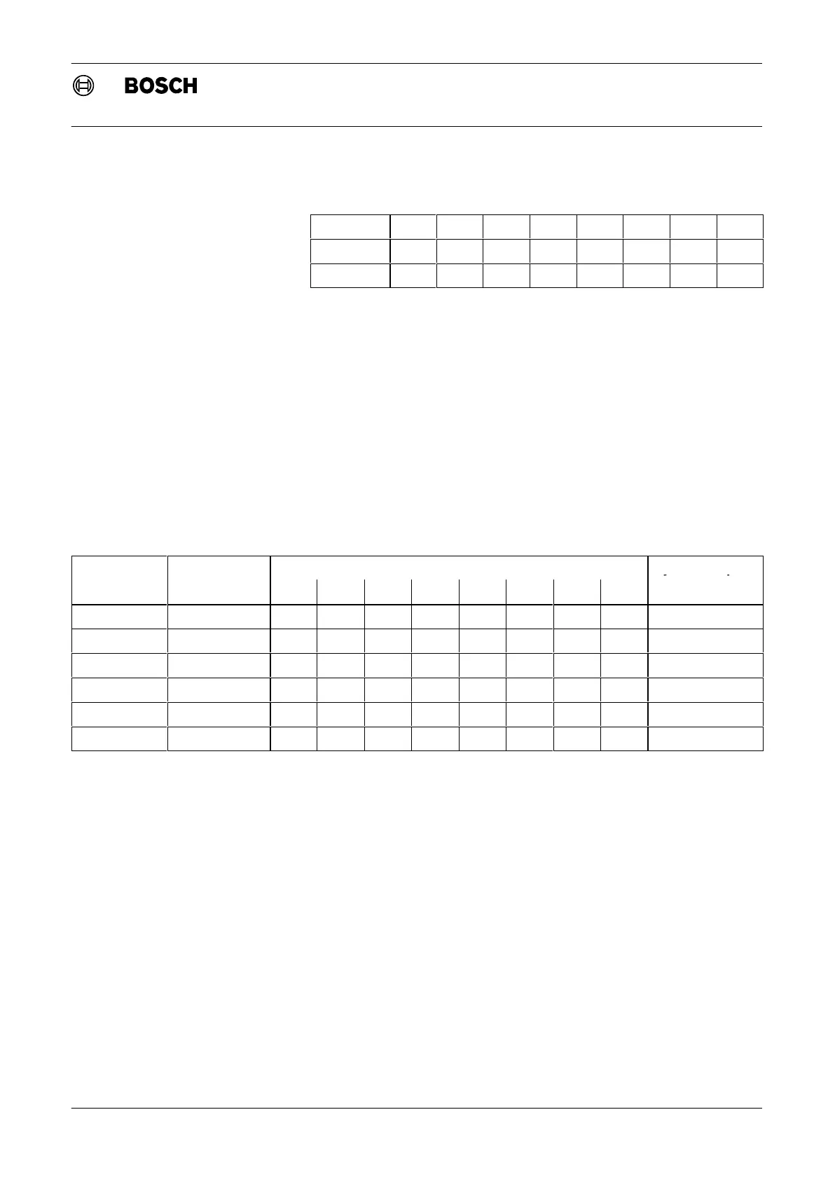
Switch
1 2 3 4 5 6 7 8
Bit value 2
0
2
1
2
2
2
3
2
4
2
5
2
6
2
7
Value 1 2 4 8 16 32 64 128
Fig. 2-7 Dip switch, value
The output modules occupy the following address ranges:
D Output module with 32 outputs occupies 4 bytes
D Output module with 16 outputs occupies 2 bytes
D Output module with 8 outputs occupies 1 byte
To avoid gaps and double assignments, the start addresses should always
be allocated as follows:
D Output module with 32 outputs: 0, 4, 8, ...
D Output module with 16 outputs: 0, 2, 4, ...
D Output module with 8 outputs: 0, 1, 2, ...
The following table shows a sample assignment.
Module
Start address
Dip switch setting
Bytes occupied
1 2 3 4 5 6 7 8
32 outputs 0 OFF OFF OFF OFF OFF OFF OFF OFF 0.0 to 3.7
16 outputs 4 OFF OFF ON OFF OFF OFF OFF OFF 4.0 to 5.7
16 outputs 6 OFF ON ON OFF OFF OFF OFF OFF 6.0 to 7.7
32 inputs 8 OFF OFF OFF ON OFF OFF OFF OFF 8.0 to 11.7
8 outputs 12 OFF OFF ON ON OFF OFF OFF OFF 12.0 to 12.7
8 outputs 13 ON OFF ON ON OFF OFF OFF OFF 13.0 to 13.7
Fig. 2-8 Addressing, output modules example