16 en | Installation Power amplifier
2023-01 | V02 | F.01U.402.247
Installation manual
Bosch Security Systems B.V.
5 Installation
–
Indicators, controls and settings, page 16
–
Connections, page 21
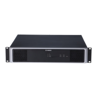
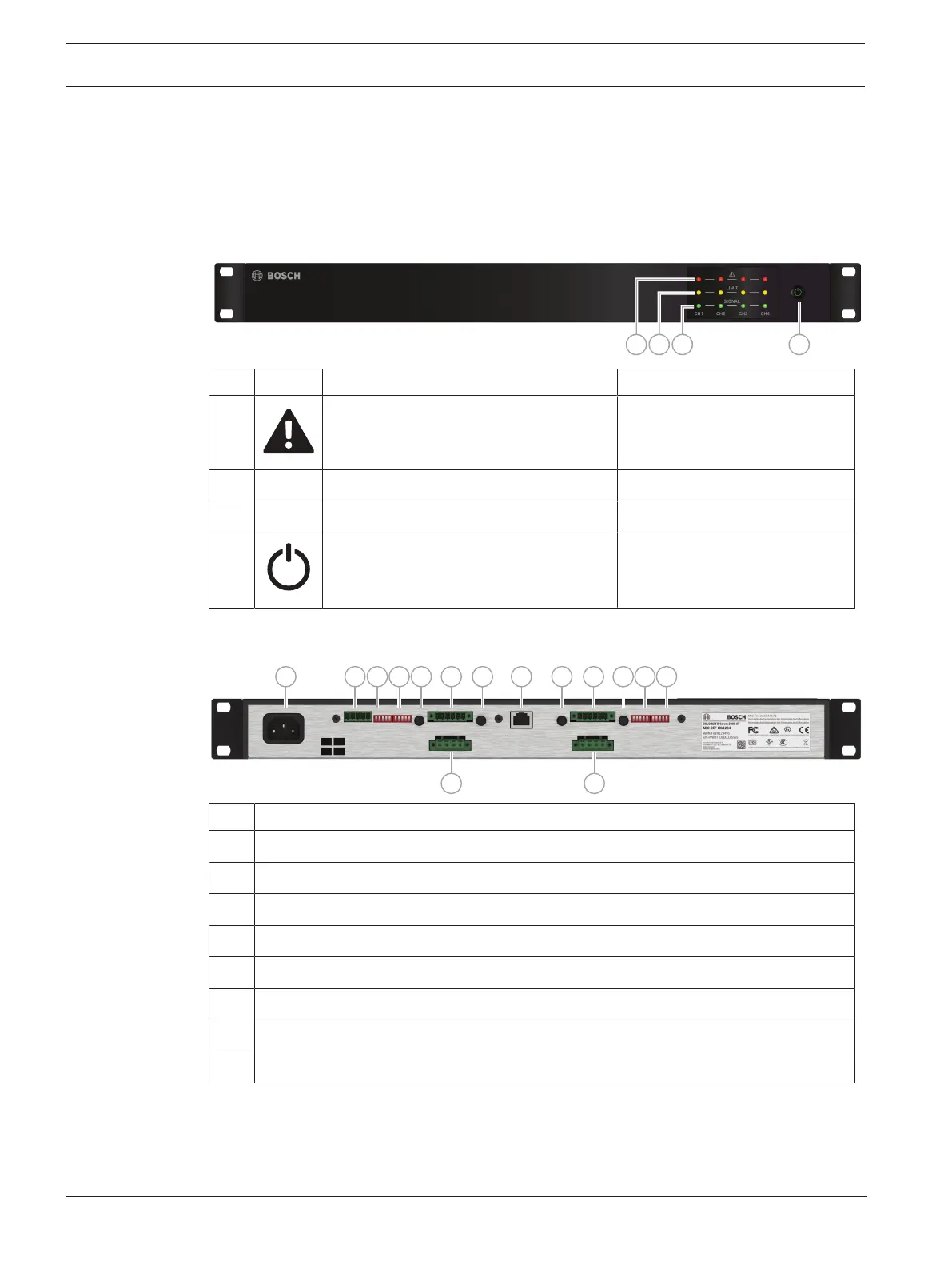
5.1 Indicators, controls and settings
Front view
LED Indicator description Color
A Device/channel fault (CH1-4) Red
B LIMIT Over driven channel (CH1-4) Yellow
C SIGNAL Input signal present (CH1-4) Green
D Power On/Off amplifier Green is ON
Blue is ecoRAIL active, or Auto
Power Down (APD) active
Rear view
1 2 3 4 6 5 7 5 6 5 3 45
88
Description
1 AC mains input socket
2 Fault relay (FLT RDY) contacts and REMOTE ON control input socket
3 AMP MODE (CH1/CH2, CH3/CH4) and DUAL-PARALLEL DIP‑switches
4 SPEAKER EQ (CH1/CH2, CH3/CH4), APD and IN1 to ALL DIP‑switches
5 LEVEL control (CH1-4)
6 Line level audio inputs socket (CH1/CH2, CH3/CH4)
7 AMP‑LINK “input” RJ45 socket
8 Loudspeaker OUTPUTS socket (CH1/CH2, CH3/CH4)