Installation 27/48
RE29583-XL-B/09.20, 4WS2EM 10...XL..., BoschRexrothAG
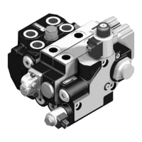
For flushing the system into which the valve is to be installed, flushing plates with
FKM seals and porting pattern according to ISO4401-05-05-0-05 are available.
For adimensional drawing of the flushing plate, refer to the "Datasheet29583-XL".
Within the flushing plate, ports P, TandT1 as well as X and Y are connected with
each other.
Fig. 2: Flushing plate, representation of the inner connections
Install this flushing plate into the system instead of the valve and subsequently
flush it.
When using the subplates mentioned under chapter 7.6 "Required accessories"
or in case of assembly on comparable cast iron installation surfaces, tighten all
four mounting screws with atightening torque of 12.5Nm ± 1.5Nm (with afriction
coefficient of µ
total
=0.09...0.14). This tightening torque refers to the maximum
admissible operating pressure.
The use of adirectional valve with portin accordance with ISO4401-05-05-0-05
is suited better than aflushing plate.
This valve can also be used for flushing the actuator ports.
The following is aguideline for the necessary flushing time t in hours:
t ≥
V
- 5
q
v
V Tank capacity in liters
q
V
Pump flow in liters / minute
The degree of contamination of the hydraulic fluid that can be monitored by
acontinuous measurement using aparticle counter is decisive for the flushing time.
Install apressure differential-resistant pressure filter without bypass, if possible
with integrated clogging indicator, directly in front of the valve. During the flushing
procedure, check all filters in short intervals and exchange the contaminated filter
elements, if necessary.

 Loading...