Apart from the indicated connections, it is necessary to wire the
Bb contact at the control section for signaling the readiness for
operation of the drive controller (see Project Planning Manual
"Rexroth IndraDrive Drive Controllers Control Sections").
For proper function of the motor thermal management connect the motor
thermal sensor as described in the wiring diagram. Otherwise motor
overtemperature sensing is not provided by the drive.
For Rexroth motors with data memory in the motor encoder, such as MSK,
the motor overload protection level is set automatically while connecting the
motor to the drive. There is no adjustment necessary. Otherwise refer to the
Rexroth firmware documentation.
4.2.2 Connection points
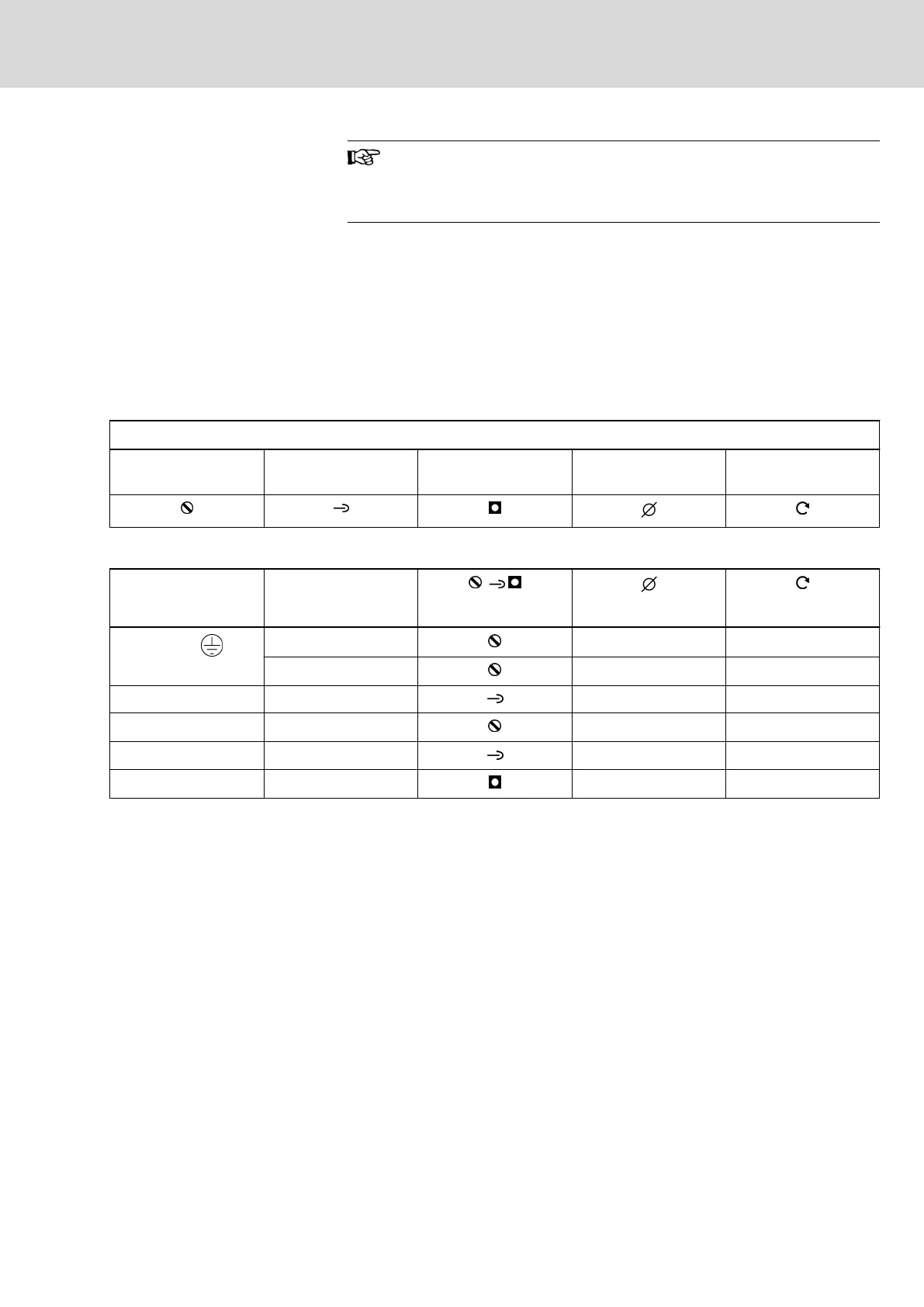
Symbols used to describe the connection points
Screw terminal block Spring terminal Thread Max. connection cross
section
Max. tightening torque
Tab. 4-1: Symbols
Connection point HCS02
mm
2
(AWG)
Nm
X3, X5,
A, B
1) 2)
4,0 (10) 0,6
C
3)
16,0 (6) 1,7
X6 A, B, C 1,5 (16) -
X9 B, C 4,0 (10) 1,7
X13 A, B, C 1,5 (16) -
L+, L- B, C M6 6,5
1) A: HCS02.1E-W0012
2) B: HCS02.1E-W0028
3) C: HCS02.1E-W0054, -W0070
Tab. 4-2: Connection points
IndraDrive Drive Controllers Power Sections HCS02 15/21
Instructions for use
R911319657_Edition 09 Bosch Rexroth AG