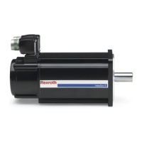
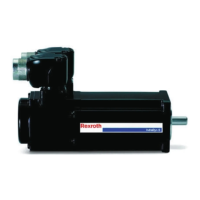
MAD/MAF
B05 (flange assembly) B35 (foot assembly)
Hole Screw (8.8) Hole Screw (8.8)
Ø [mm] Type M
A
[Nm] with µ
G
0.12
Ø [mm] Type M
A
[Nm] with
µ
G
0.12
100 14 M12 84 11 M10 48
130
18 M16 206
12 M10 48
160 14
M12 84
180 14.5
225 22 M20 415
M
A
Tightening torque in Newton meters
µ
G
Coefficient of friction
Tab. 8-1: Mounting holes and screw tightening torques
● When mounting the motor, avoid clamping or jamming the
centering bundle on the motor side.
● Avoid damaging the receptacle fit on the plant side.
● Use for all kinds of mounting the existing motor fastening
holes to fasten the motor safely onto the machine.
Check the property and accuracy of the connection before you do
the electric connection.
Foot assembly
Before attaching the IndraDyn A motors according to the foot assembly meth‐
od, observe the clearance from the center of the motor shaft to the bottom
edge of the foot specified in the particular motor dimension drawing. Com‐
pare this clearance with the connection clearance actually present on the ma‐
chine.
The mounting holes and clearances correspond to the general tol‐
erance according to ISO 2768-m.
If attaching the motors according to the foot assembly method, proceed as
follows:
1. Dismount the lower lateral air baffles (only for MAD130 ... 225) to have
free access to the mounting holes.
2. Align the motor such that the center line of the motor shaft is flush with
the center line of the connection shaft of the machine. Support the motor
on sheet steel strips when aligning it.
3. Firmly connect the motor to the machine (for tightening torques, see Fig.
8-1).
4. Reattach the air baffles to the motor.
Bosch Rexroth AG DOK-MOTOR*-IDYN*A*EXPD-IB05-EN-P32/69
Rexroth MAD and MAF Motors in EX px d Design acc. to ATEX Directive 2014/34/EU
Mechanical attachment

 Loading...


