20/36 Commissioning
Bosch Rexroth AG, Valve amplifier VT-MSPA, RE 30232-B/08.2020
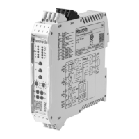
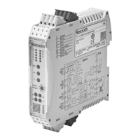
8.2 Block circuit diagram VT-MSPA2-2X
XH2
A
B
XH1
V
1
2
10
9
5
6
12
11
Zw -1
(2)
(5)
(11)
(12)(10)
(12)(10)
(9)
(9)
(7)
(6)
(8)
(14)
(13)
(15)
(4) (3)
8
4
3
7
U
U
0V
+24V
+U
KBA
tt
tt
t
tt
tt
I
A
I
A –
I
B
I
B
t
KBB
KBA
KBB
MO
-U
U
U(I)
U
U
U
U
ab
U
U
U
U
+In
-In
DI
-Out
+Out
G
x
y
B
S
G
PWM
PID
PWM
PID
B
S
G
Enable
Enable
Logic
Actual
value
Supply
voltage
Command
value
Digital input
Ready for
operation
Test jack
Cable break
Cable break
Enable
1 Power supply unit 2 Differential amplifier 3 Command value summator
4 Zero point adjustment 5 Inversion 6 Simple ramp
7 4-quadrant ramp 8 Command value attenuator 9 Characteristic curve generator
10 Current regulator
11 Clock pulse generator 12 Output stage
13 Enable or inversion or ramp off or
4Q ramp
14 Switching logic/error detection 15 Digital output

 Loading...


