Subject to change without prior notice Revised 05-12
6 720 220 046
12 TA Series
2. Long length thermostat and control wiring leads
may create voltage drop. Increase wire gauge or
up-size transformers may be required to insure
minimum secondary voltage supply.
3. FHP recommends the following guidelines for
wiring between a thermostat and the unit: 18 GA
up to 60 foot, 16 GA up to 100 ft and 14 GA up to
140 ft.
4. Do not apply additional controlled devices to the
control circuit power supply without consulting
the factory. Doing so may void equipment
warranties.
5. Check with all code authorities on requirements
involving condensate disposal/over ow
protection criteria.
SEQUENCE OF OPERATION
Cooling Mode
See Typical Wiring Diagram page 24. Energizing the
“O” terminal energizes the unit reversing valve in the
cooling mode. The fan motor starts when the “G”
terminal is energized.
When the thermostat calls for cooling (Y), the loop
pump or solenoid valve if present is energized and
compressor will start.
Once the thermostat is satised, the compressor
shuts down accordingly and the fan ramps down to
either fan only mode or off over a span of 30 seconds
(ECM Motors).
Note that a fault condition initiating a lockout will
de-energize the compressor.
Heating Mode
Heating operates in the same manner as cooling,
but with the reversing valve de-energized. The
compressor will run until the desired setpoint
temperature on the thermostat is achieved.
Once the thermostat is satised, the compressor
shuts down and the fan ramps down in either fan
only mode or turns off over a span of 30 seconds.
Auxiliary electric heating coils are not available on
the EP product line.
ELECTRIC HEATER PACKAGE OPTION
Factory installed internal electric heater packages are
available for all series units. Two power supplies are
required when heater packages are utilized. The power
supply for the heater package (located in the electric
heater package control box) provides power for the
heater elements, the blower motor and the control
circuit for the unit. The power supply for the unit
provides power for the compressor. This allows the
electric heaters to continue to operate along with the
blower motor in the case of unit compressor and/or
compressor power supply failure. Each TA Series
model has a number of heater sizes available. Refer to
Electric Heater Package Option
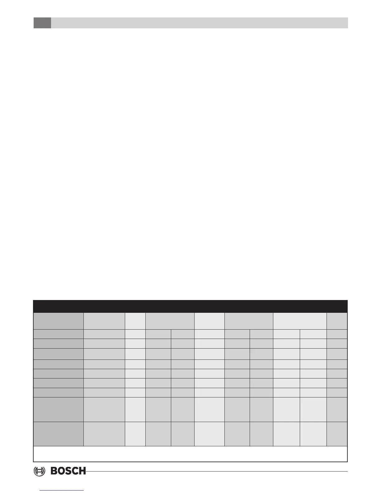
Figure 8: Heater Package Compatibility
Model Heater Model KW Heater Amps Circuit MCA Max. Fuse AWG
Min.
208V 240V 208V 240V 208V 240V
TA025 thru 035 HP050-1XS 4.8 17.3 20.0 L1/L2 27.1 30.4 30 30 8
TA049 thru 071 HP050-1XM 4.8 17.3 20.0 L1/L2 27.1 30.4 30 30 8
TA025 thru 035 HP075-1XS 7.2 23.6 30.0 L1/L2 34.9 42.9 40 45 8
TA049 thru 071 HP075-1XM 7.2 23.6 30.0 L1/L2 35.7 43.8 40 45 8
TA025 thru 035 HP100-1XS 9.6 34.7 40.0 L1/L2 48.8 55.4 50 60 6
TA049 thru 071 HP100-1XM 9.6 34.7 40.0 L1/L2 49.5 56.3 50 60 6
TA049 thru 071 HP150-1XM
HP150-1XM
14.4
14.4
52.0
34.7
17.3
60.0
40.0
20.0
SINGLE
L1/L2
L3/L4
71.2
49.5
21.7
81.3
56.3
25.0
80
60
25
90
60
25
4
6
10
TA049 thru 071 HP200-1XM
HP200-1XM
19.2
19.2
69.3
34.7
34.7
80.0
40.0
40.0
SINGLE
L1/L2
L3/L4
92.9
49.5
43.4
106.3
56.3
50.0
100
50
45
110
60
50
2
6
6
All heaters rated single phase 60 Hz, and include unit fan load. All fuses type “D” time delay or HACR type breaker or
HRC FORM 1. Wire size based on 60 deg. C copper conductors.
 Loading...