6 720 220 046
Revised 05-12
3
TA Series
Table of Contents
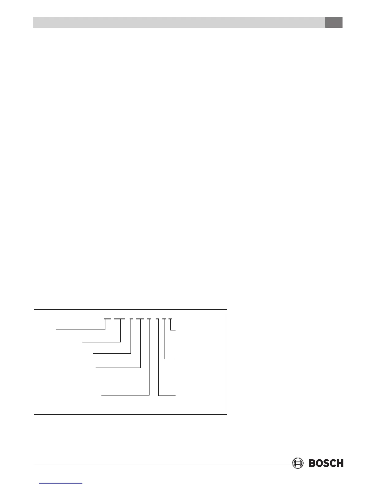
MODEL NOMENCLATURE
SUPPLY AIR LOCATION:
T - TOP (VT ONLY)
E - END BLOW (HZ ONLY)
B - BOTTOM (CF ONLY)
RETURN AIR LOCATION:
S - STRAIGHT THRU
(HZ ONLY)
L - LEFT
R - RIGHT
WATER CONNECTION
LOCATION:
F-FRONT
SERIES:
TA
NOMINAL CAPACITY:
VOLTAGE DESIGNATIONS:
1 - 208/1/60 & 230/1/60
CABINET CONFIGURATION:
VT - VERTICAL
HZ - HORIZONTAL
CF - COUNTERFLOW
HEAT EXCHANGER MATERIAL:
C - COPPER
N - CUPRO-NICKEL
TA 049 - 1 VT C - F L T
TABLE OF CONTENTS
Model Nomenclature ......................................................3
Initial Inspection ............................................................4
General Description .......................................................4
Moving And Storage .......................................................4
Safety Considerations ....................................................4
Location .........................................................................4
Installation .....................................................................4
Mounting Vertical Units ..................................................4
Mounting Horizontal Units .............................................5
Condensate Drain ..........................................................5
Duct System ...................................................................6
Piping .............................................................................6
Electrical ........................................................................6
Ecm Interface Board Thermostat Connections .............7
Safety Devices And The UPM Controller ........................9
Sequence Of Operation ...............................................12
Electric Heater Package Option ...................................12
Sequence Of Operation Two Stage Units .....................13
Cooling Mode ..............................................................13
Heating Mode ..............................................................13
Well Water Systems ......................................................13
Installation Of Pressure Regulating Valves ...................13
Cooling Tower/Boiler Systems .....................................14
Earth Coupled Systems ...............................................14
System Checkout .........................................................14
Unit Start-Up ................................................................14
Heat Recovery Package ...............................................15
Typical Connection Piping ...........................................15
Water Tank Preparation: ...............................................15
HR Water Piping: ..........................................................16
Water Tank Rell: .........................................................16
Initial Start-Up: ............................................................16
Maintenance ................................................................17
Typical Wiring Diagrams ...............................................21
Operating Pressures & Temperatures ..........................23
Unit Check-Out Sheet ..................................................27
Troubleshooting ...........................................................28
 Loading...