Subject to change without prior notice Revised 05-12
6 720 220 046
16 TA Series
6. Close all valves and remove the drain hose.
7. Install HR water piping.
HR WATER PIPING:
All hot water piping should be a minimum of 3/8t
O.D. copper tube to a maximum distance of fteen
(15) feet. For distances beyond fteen feet but not
exceeding sixty (60) feet use 1/2” copper tube.
Separately insulate all exposed surface of both
connecting water lines with 3/8” wall closed cell
insulation. Install isolation valves on supply and
return to the heat recovery. (Figure #9)
WATER TANK REFILL:
1. Open the cold water supply to the tank.
2. Open a hot water faucet to vent air from the system
until water ows from the faucet, then close.
3. Depress the hot water tank pressure relief valve
handle to ensure there is no air remaining in the tank.
4. Carefully inspect all plumbing for water leaks.
Correct as required.
5. Purge all air from HR by depressing the schrader
valve on the HR Unit. Allow all air to bleed out
until water appears at the valve.
6. Before restoring the power or fuel supply to the
water heater, adjust the temperature setting on
the tank thermostat(s) to ensure maximum
utilization of the heat available from the
refrigeration system and conserve the most
energy. On tanks with both upper and lower
elements and thermostats, the lower element
should be turned down to 100° F, while the
upper element should be adjusted to 120° F.
Depending upon the specic needs of the
customer, you may need to adjust the upper
element differently. On tanks with a single
thermostat lower the thermostat setting to 120°
F or the “LOW” position.
7. After thermostat adjustments are completed,
replace access cover and restore electrical or
fuel supply to water heater.
INITIAL START-UP:
1. Make sure all valves in heat recovery water
piping system are open. NEVER OPERATE HR
PUMP DRY.
2. Turn on the heat pump. The HR pump should not
run if the compressor is not running.
3. Turn HR switch to the “ON” position. The pump
will operate if entering water temperature to HR
is below 120° F.
4. The temperature difference between the water
entering and leaving the heat recovery should be
5° to 15° F.
5. Allow the unit to operate for 20 to 30 minutes to
ensure it is functioning properly. The pump
should shut off when the water temperature
entering the heat recovery reaches 120°F.
Initial Start-UP
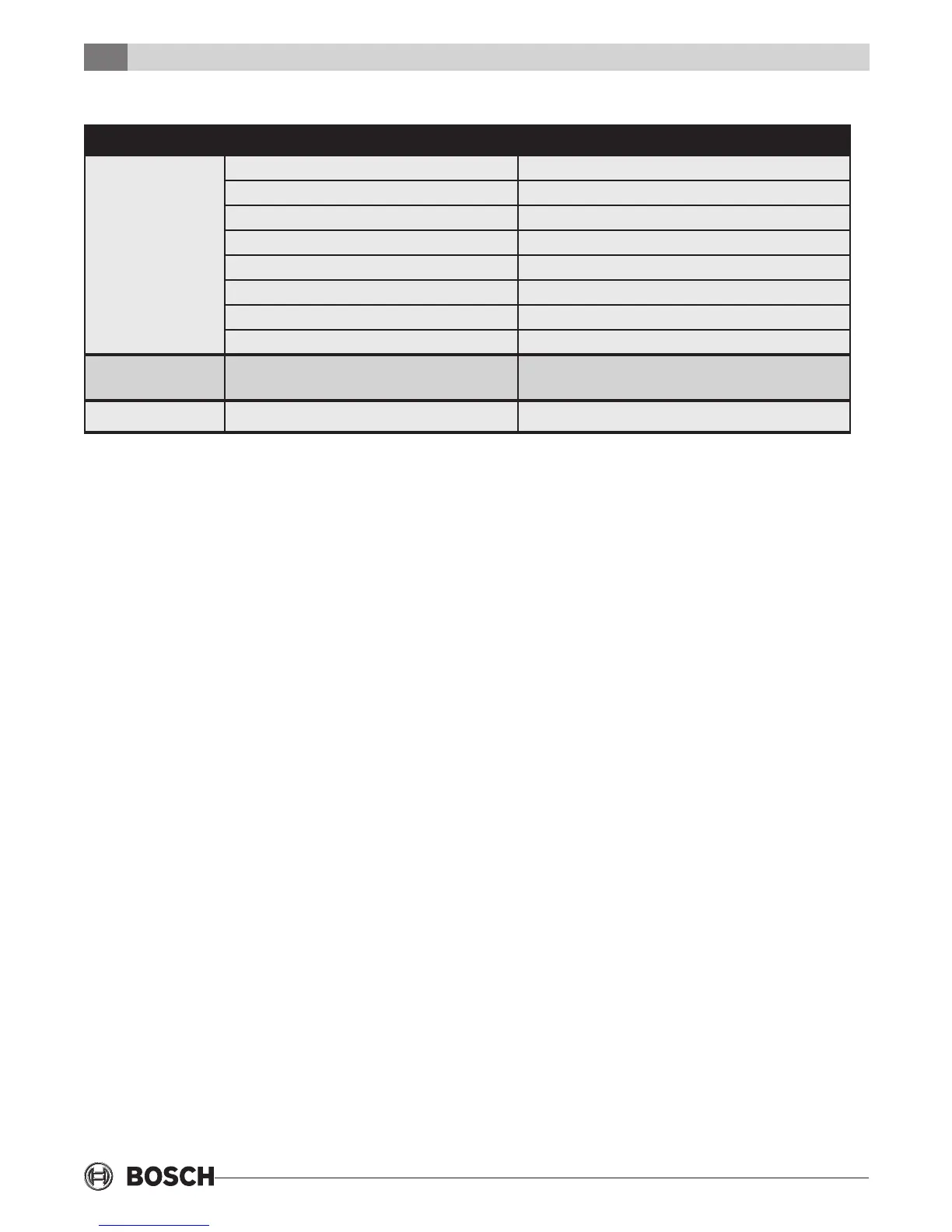
TROUBLESHOOTING
Problem Possible Cause Checks and Corrections
No Flow
Low Flow
No Power Check power supply
On/Off Switch Position Set switch to “ON” position
Compressor Contactor Engage heat pump contactor
Broken or loose wires Repair or tighten wires
Air Lock Purge air from piping system
Stuck pump shaft/impeller Remove pump cartridge and clean
Defective pump Replace pump
Kinked or under sized water piping Repair kink and check for proper line size
High Water
Temperature
Water temp limit closed Stuck limit switch
Sensor not attached securely to line
Low Heat Output
Scaled or fouled heat exchanger Clean heat exchanger
 Loading...