6 720 220 046
Revised 05-12
5
TA Series
pan is usually placed on a plywood base isolated
from the ceiling joists by additional layers of
vibration absorbing mesh. In both cases, a 3/4”
drain connected to this secondary pan should be
run to an eave at a location that will be noticeable.
If the unit is located in a crawl space, the bottom of
the unit must be at least 4” above grade to prevent
ooding of the electrical parts due to heavy rains.
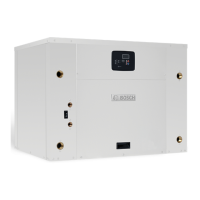
CONDENSATE DRAIN
A drain line must be connected to the heat pump
and pitched away from the unit a minimum of 1/8”
per foot to allow the condensate to ow away from
the unit.
This connection must be in conformance with local
plumbing codes. A trap must be installed in the
condensate line to insure free condensate ow.
(Heat Pumps are not internally trapped). A vertical
air vent is sometimes required to avoid air pockets.
(See Figure #3). The length of the trap depends on
the amount of positive or negative pressure on the
drain pan. A second trap must not be included.
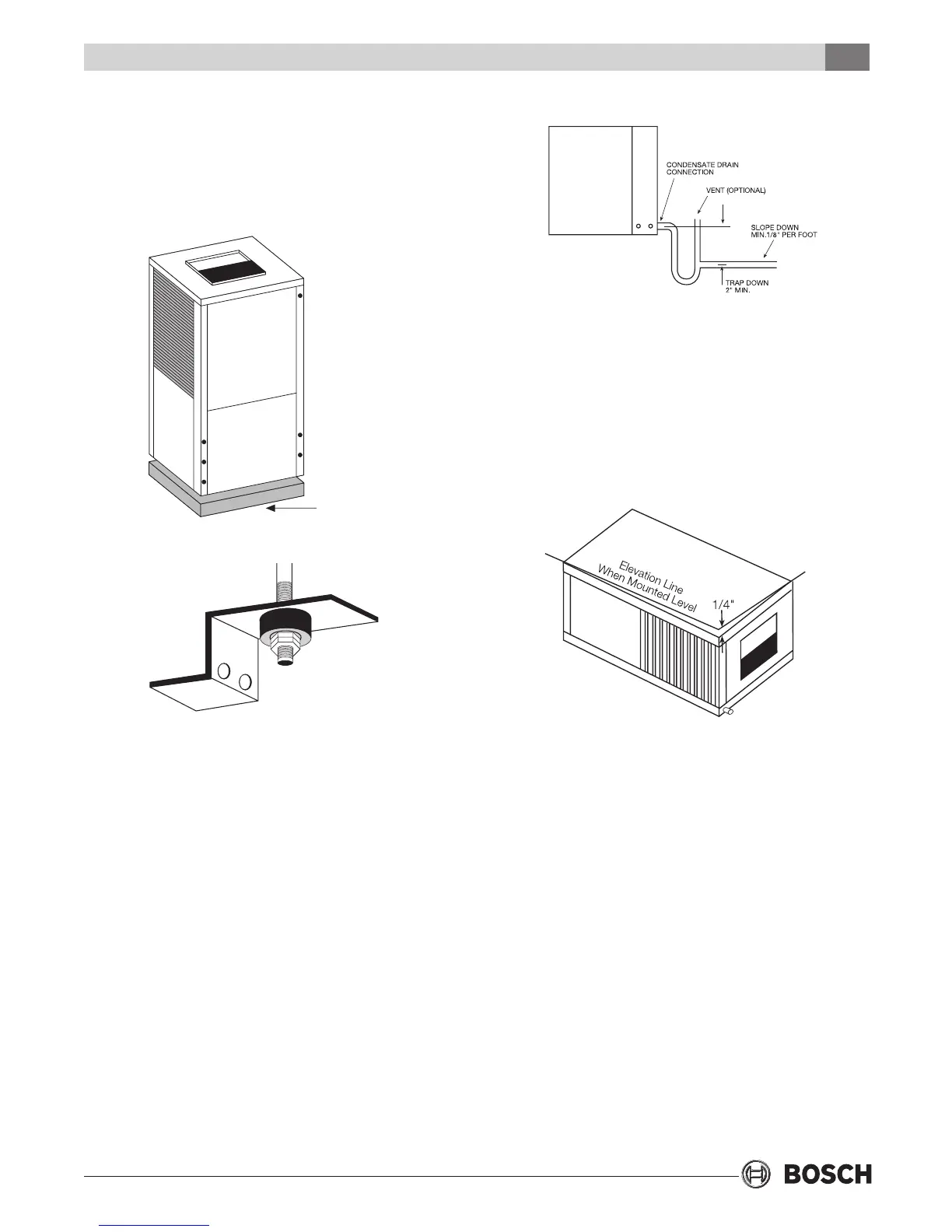
The horizontal unit should be pitched
approximately 1/4” towards the drain in both
directions, to facilitate condensate removal. (See
Figure #4)
Figure #4
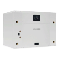
slightly larger than the base to minimize vibration
transmission to the building structure. It is not
necessary to anchor the unit to the oor.
(See Figure #1).
MOUNTING HORIZONTAL UNITS
While horizontal units may be installed on any level
surface strong enough to hold their weight, they are
typically suspended above a ceiling by threaded rods.
The rods are usually attached to the unit corners by
hanger bracket kits. (See Figure #2). The rods must be
securely anchored to the ceiling. Refer to the hanging
bracket assembly and installation instructions for
details. Horizontal units installed above the ceiling
must conform to all local codes. An auxiliary drain pan
if required by code, should be at least four inches
larger than the bottom of the heat pump. Plumbing
connected to the heat pump must not come in direct
contact with joists, trusses, walls, etc.
Some applications require an attic oor installation
of the horizontal unit. In this case the unit should
be set in a full size secondary drain pan on top of a
vibration absorbing mesh. The secondary drain pan
prevents possible condensate overow or water
leakage damage to the ceiling. The secondary drain
VIBRATION
PAD
FULL SIZE
Figure #1
Figure #2
Figure #3
Mounting Horizontal Units
 Loading...