Service and Spares
Greenstar Danesmoor Utility
2022+
and Utility System
2022+
- 6 721 846 263 (2022/01) 51
7.12 Re-commissioning the burner
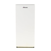
Fig. 88 18/25 and 25/32 Burner O-ring seal shown
1. Align burner combustion head into burner collar.
▶ Locate the burner retainer [A] over the threaded lug on the collar [B],
ensure that the burner is level and push the burner firmly onto the
flange ensuring the O-ring seal is fully engaged. Support the burner in
position and secure with the retaining nut [C]. Tighten sufficiently to
hold the burner but do not over tighten.
▶ Check that the burner is seated correctly on its mounting flange and
that the oil hose/s are routed correctly as shown in Fig. 90 and not
trapped in front of or underneath the burner.
▶ Attach air duct pipe and tighten clip (D) to secure to the burner air
intake.
Fig. 89 Refitting the burner
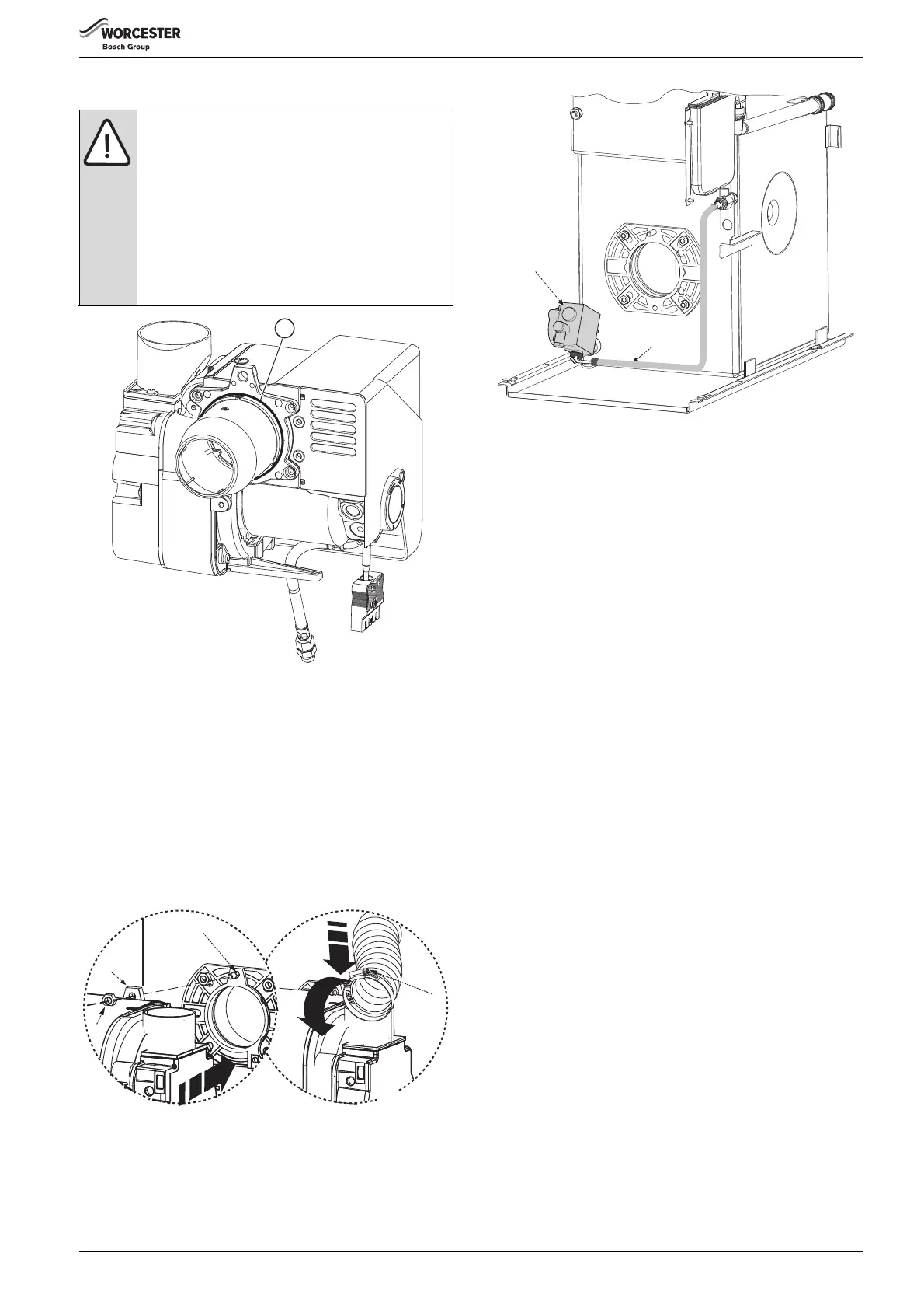
Fig. 90 Oil pump and hose detail
[1] Oil pump
[2] Flexible oil hose route. Ensure that the rigid 90° connection at the
pump points to the right when the boiler is viewed from the front
and the flexible hose follows the route as show in the figure above.
2. Swing control box back up into operating position and retain in place
by replacing the two securing screws (E) in the bottom locations.
▶ Plug burner lead (F) into control box.
▶ Connect an oil pressure gauge to the oil pump, run the burner and
check the oil pressure is correct for the required boiler output. Check
that the smoke reading is between 0 - 1. If above 1 check the air
setting. If the air setting is correct check that the burner has been
reassembled correctly.
Allow the boiler to warm up then check the combustion settings are
correct as indicated in table 10 on page 44, ensure CO
2
levels are
correct. Adjust the air shutter if necessary see page 44, figure 70 for
details.
When the combustion is correct turn off the boiler, remove the
pressure gauge and refit the blanking plug and plastic cover.
3. Locate the front panel by aligning the ball studs with the retaining
slots and secure near the top and at the bottom by gently pushing
home the ball studs into the retaining slots (I). Remember always to
apply pressure at the edges of the panels to avoid damage.
WARNING: Flue gas leakage
The seal between the burner and the mounting flange
must form a gas tight seal to prevent leakage of
potentially dangerous gas from the combustion
chamber.
▶ Unless the burner is level when pushing the burner
into the flange the O-ring may not seat properly
allowing flue gas to escape!
▶ Always check that the O-ring seal (Fig 88item A) is in
good condition before fitting the burner.
Replace the O-ring seal if defective.
6720821683-25.1Wo
A
 Loading...