Page 22 Installation and Operating Guide English
Installation and Operating Guide pro.Bose.com
Product Overview
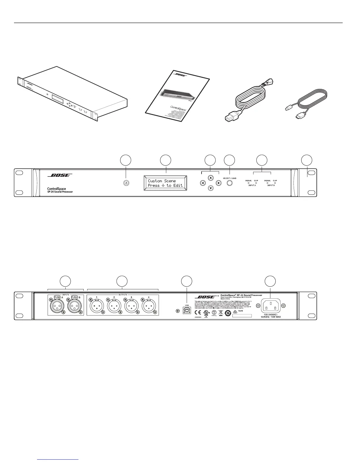
In the Box
The product box includes the following items:
ControlSpace
®
SP-24 sound processor Installation & Operating Guide AC power cord USB cable
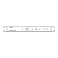
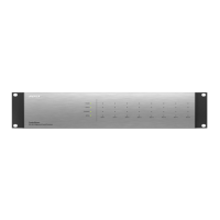
Front Panel Controls and Indicators
1. Power button: On/Off
2. Display: The 2 x 16 backlit LCD displays Preset names and parameter values.
3. Navigation controls: Press to navigate through the user interface.
4. SELECT/LOAD: Loads Presets and Custom Scenes. Saves Utility Menu parameters.
5. SIGNAL/CLIP LEDs: Illuminates to show signal and clipping indication for each input channel.
6. Removable rack ears: For use when installing unit into rack mount enclosures.
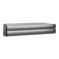
Rear Panel Connections
1. Inputs A/B: Balanced XLR Inputs.
2. Outputs 1-4: Balanced XLR Outputs.
3. USB port: B-type USB port for optional connection to PC running SP-24 Editor software.
4. Input power: Power cord input.
1 3 4
2
51 3 4 6
2