23
DISASSEMBLY PROCEDURES
DANGER: SHOCK HAZARD
The PowerMatch
®
amplifiers have high voltage (up to 400 VDC) on the heatsink and
much of the circuitry on the power supply PCB during operation. In addition, the power amplifier
PCBs have a large amount of capacitance on the boards that retain a dangerous charge for a
significant period of time.
- DO NOT touch the power supply heatsink when the amplifier is operating.
- DO NOT use the power supply heatsink as a ground point for test equipment. Damage
to your equipment could result.
- Allow at least five (5) minutes after operation before removing the cover or attempting to
replace a PCB assembly.
Note: The PowerMatch amplifiers are constructed differently than a typical amplifier chassis.
What would normally be the top cover is on the bottom of the chassis. To remove this cover, you
must place the unit upside-down on your bench.
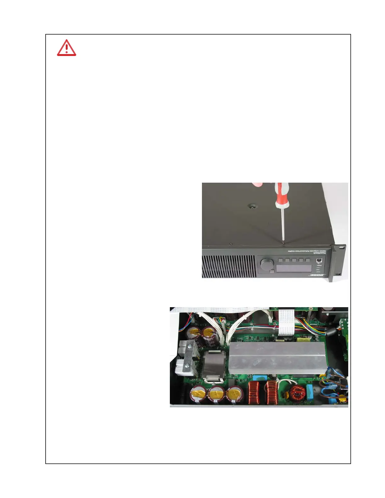
1. Cover Removal
1.1 Remove the 17 screws that secure the
cover to the chassis. Be sure to use the
correct screwdriver size to avoid stripping
the screw heads. Be sure to remove the 2
screws located in the middle of the cover.
Lift off the cover.
2. Power Supply PCB Removal
2.1 Disconnect the chassis from AC mains.
2.2 Wait at least five (5) minutes to allow the
power supply capacitors to discharge.
Perform procedure 1.
2.3 Unplug the Faston connectors
at locations P1 and P2 that run
from the AC inlet PCB. Unplug the
connectors that connect to the
amplifier PCBs at connectors PL1
and PL2. Unplug the ribbon cable
that runs to the digital PCB at
connector SK1.
2.4 Lift off the plastic shield that
covers the power supply heatsink.
Lift off the plastic heatsink tunnel
located at the front of the board.
Retain for re-use on the replacement board.
2.5. Remove the six screws and one standoff that secure the power supply PCB to the chassis.
Slide the board off of the slotted head standoffs and carefully lift the board
out of the chassis. Take care to not flex the board during removal.
 Loading...


