24
DISASSEMBLY PROCEDURES
3. Digital PCB Removal
3.1 Disconnect the chassis from AC mains.
3.2 Wait at least five (5) minutes to allow the power supply capacitors to discharge. Perform
procedure 1.
3.3 If the unit is a network capable unit (i.e. PM8500N) and has a digital audio card installed,
remove the two screws at the rear of the chassis that secure it and slide out the digital audio
card.
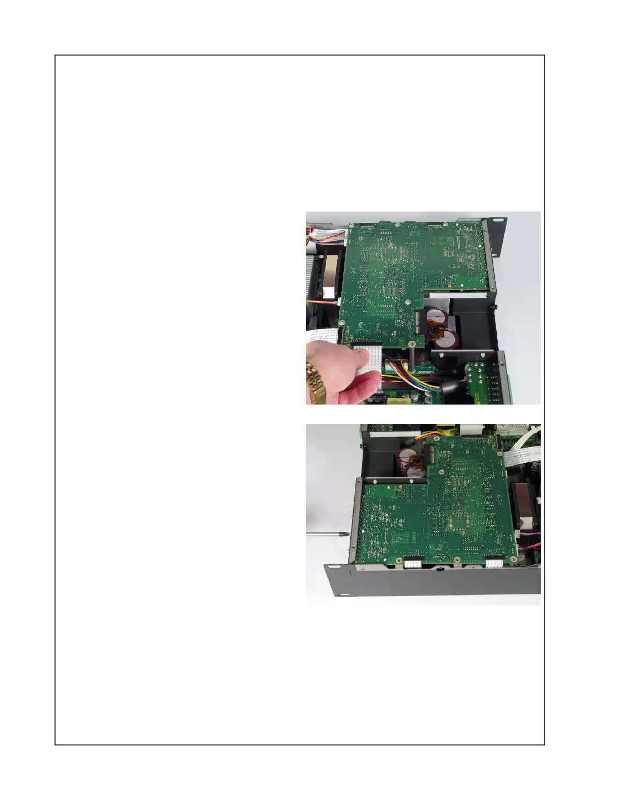
3.4 Unplug the ribbon cable to the power
supply PCB at connector J8. Unplug the two
ribbon cables to the amplifier PCBs at J13
and J14. Unplug the wiring harnesses to the
three fans at J9, J10 and J11. Unplug the
ribbon cable to the display board at J17.
3.5 On the back of the chassis, remove the
eight screws that secure the digital PCB
and the analog input PCBs to the chassis.
3.6 Remove the five screws on the top of the
digital board that secure the digital / analog
input PCB subassembly to the chassis. Slide
them forward off of the chassis locating tab
and lift out the boards.
Re-assembly Note: When mounting the
digital / analog board subassembly back in
the chassis, do not install a screw in the
location nearest the output boards. This is
where the screw that goes through the cover
is installed.
4. Analog Input Board Removal
4.1 Perform procedure 3.
4.2 Compress the ends of the three plastic standoffs that secure the analog board to the digital
board. Slide the analog board off of the connector to the digital board.
 Loading...


