27
7. Output PCB Removal
Note: There are 2 different versions of the output PCB, one with a long wiring harness to
Amp 1 and one with a short wiring harness to Amp 2. Be sure to order the correct version when
ordering a replacement PCB assembly. 4-channel amplifiers use only the short harness board.
7.1 Disconnect the chassis from AC mains.
7.2 Wait at least five (5) minutes to allow the power supply capacitors to discharge. Perform
procedure 1.
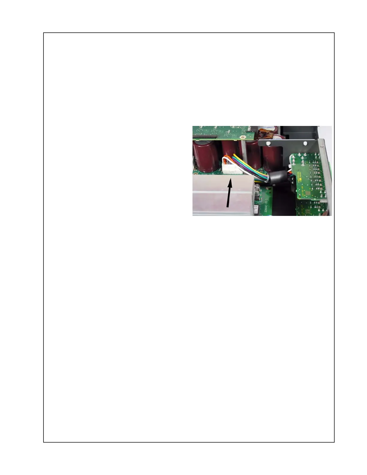
7.3 Unplug the wiring harness from the
amplifier PCB at J-AMP-OUT.
7.4 On the back of the amplifier, remove the
two screws that secure the output PCB to
the chassis. Lift out the output PCB.
8. AC Inlet PCB Removal
8.1 Disconnect the amplifier from AC mains.
8.2 Wait at least five (5) minutes to allow the power supply capacitors to discharge. Perform
procedure 1.
8.3 Disconnect the two wires at the power supply PCB at Faston connectors P1 and P2.
8.4 Remove the nut, lock washer and washer that secure the green ground wire to the chassis.
8.5 On the side of the chassis, remove the one screw that secures the AC inlet PCB assembly
to the chassis. Slide the AC inlet PCB off of the slotted standoffs. Lift out the board.
DISASSEMBLY PROCEDURES
 Loading...


