26
6. Display PCB Removal
6.1 Disconnect the chassis from AC mains.
6.2 Wait at least five (5) minutes to allow the
power supply capacitors to discharge.
Perform procedure 1.
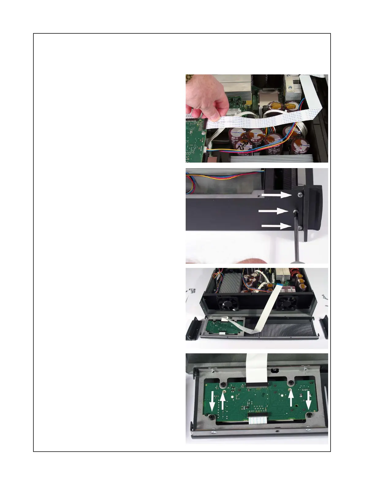
6.3 Unplug the ribbon cable on the digital
PCB at J17.
6.4 On the outside top front edge of the
chassis, remove the three screws that
secure the front panel to the chassis.
6.5 Remove the six screws that secure the
front panel assembly to the chassis at the
front rack ears.
Lift off the front panel assembly.
6.6 Remove the four screws that secure the
keypad / display subassembly to the front of
the chassis. Lift out the display subassembly
through the front panel.
DISASSEMBLY PROCEDURES
 Loading...


