9
Basic Wiring - Inputs
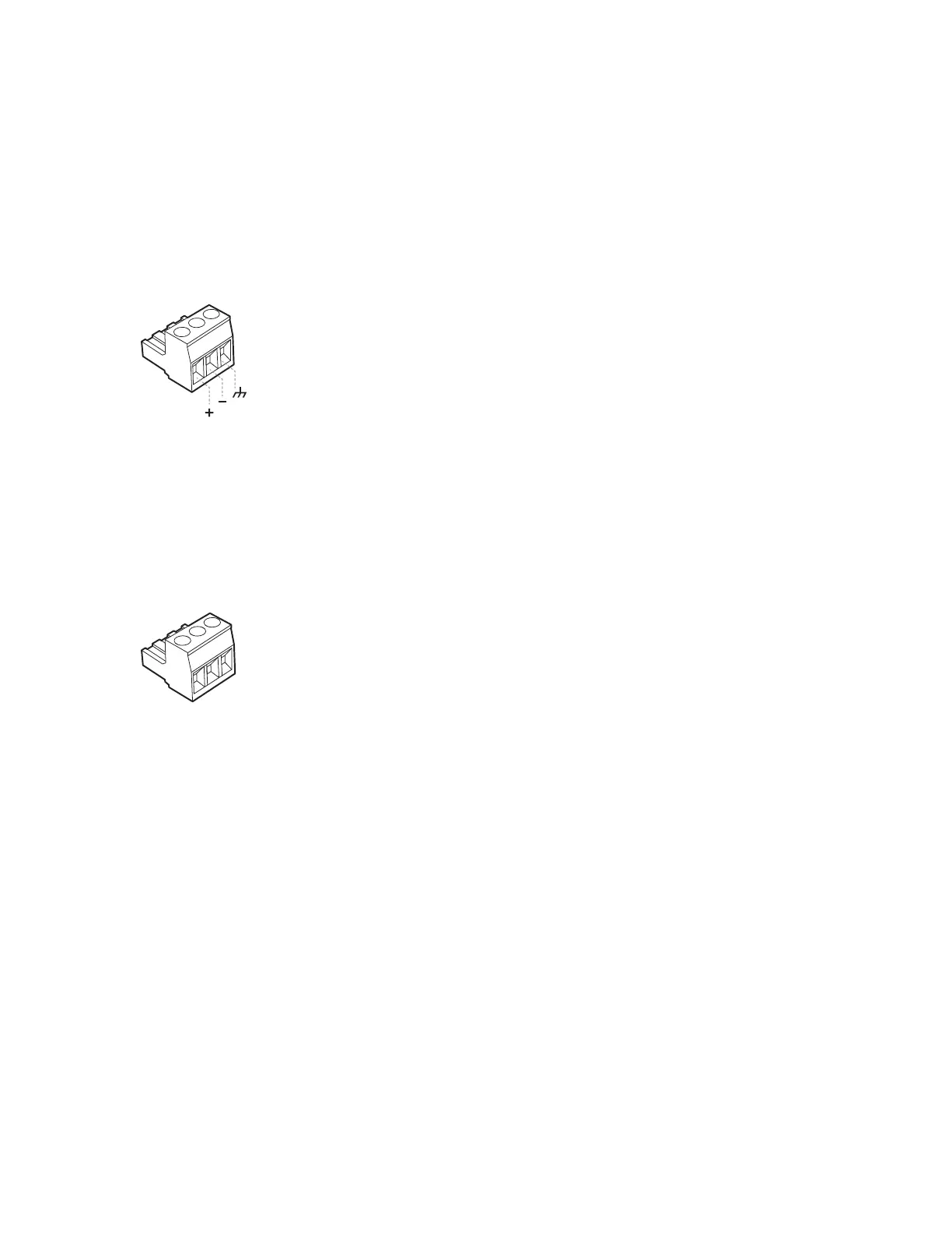
The balanced line-level analog inputs utilize 3-pin terminal block connectors (Phoenix #1776168
supplied in Connector Accessory Pack, Bose part number 343511-0010). For balanced inputs,
strip the wire ¼ inch (6mm) and connect the respective positive, negative, and ground terminals
as indicated on the unit and as shown below. For unbalanced inputs, the connector should be
wired with Pin 1 = positive, with Pin 2 and Pin 3 connected with a jumper wire and then con-
nected to the input cable shield.
Analog Input Connector
Basic Wiring – Fault Notification Output (Watchdog)
The PowerMatch
®
amplifiers feature a fault-notification circuit which outputs an electrical signal
to a 3-pin terminal block connector (orange-color Phoenix #1976010 supplied).
Pin assignments are: Pin-1 = Normally Closed; Pin-2 = Common; and Pin-3 = Normally Open.
Fault Notification Output Connector
Basic Wiring - Outputs
The loudspeaker outputs utilize two (2) high-current, 8-pin locking terminal block connectors
(Phoenix COMBICON #1778120) that accept cables from 10 to 24 AWG in diameter.
Note: The terminal block utilizes a +/- screw head (see Figure 8) and should be tightened using
either a +/- head or flat-bade screw driver; a Philips-head screwdriver is not recommended.
The wiring of the connector varies by amplifier output configuration. The output connector wiring
for mono (single channel) and voltage-bridge configurations are printed on the rear panel of each
unit. The I-Share and Quad-Bridge configurations require installing a shorting jumper (supplied
in Connector Accessory Pack, Bose part number 343511-0010). See Figure 9 for placement of
shorting jumper pins in output connector. When both jumpers are correctly placed, the first and
last position of the connector should be empty. Placement of the shorting jumper is identical for
I-Share and Quad Bridge modes. For connection of loudspeaker wiring, refer to the figures on
the next page for I-Share and Quad Bridge configurations.
For the I-SHARE and QUAD-BRIDGE configuration pin assignments, please refer to the Output
Power Configuration section of this document.
Pin 3
Pin 2
Pin 1
Pin 3
Pin 2
Pin 1
 Loading...


