Installation Guide
English 23
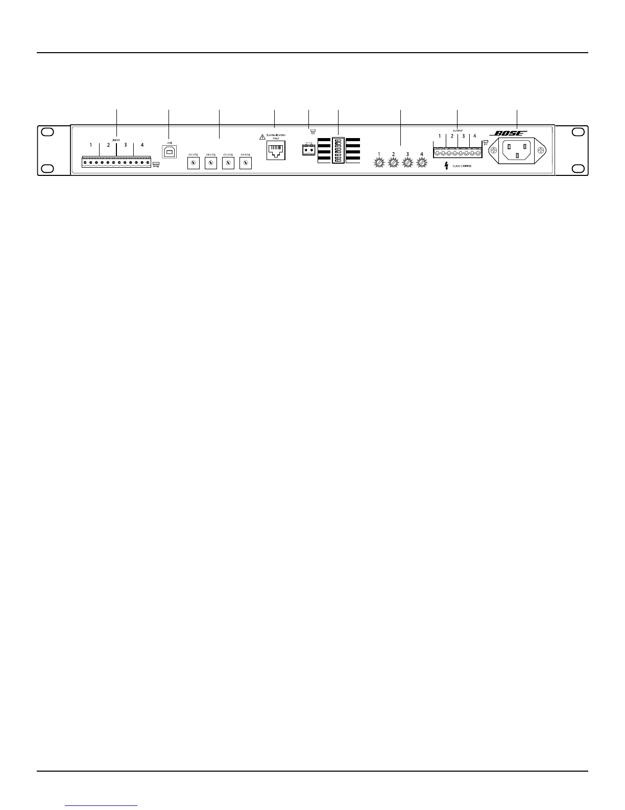
Front and Rear Panels
pro.Bose.com
0
-∞
0
-∞
0
-∞
0
-∞
MUTE
AUTO STANDBY
SENSITIVITY
GLOBAL OUT
OUTPUT 1
OUTPUT 2
OUTPUT 3
OUTPUT 4
CONFIG
ON
Low Z
SOFTWARE
12 dBu
100V
Low Z
OFF
Hi Z
REAR
4 dBu
70V
Hi Z
Low ZHi Z
Low ZHi Z
1. FLAT
2. DS16
3. DS40
4. DS100
100-240V ~ 50/60Hz 700W MAX
PowerShare
PS604
5. FS3B
6. 402
7. 802
8. MA12EX
9. RMU105
0. RMU108
4
6
9
0
7
8
3
2
1
5
4
6
9
0
7
8
3
2
1
5
4
6
9
0
7
8
3
2
1
5
4
6
9
0
7
8
3
2
1
5
OUTPUT ATTENUATION
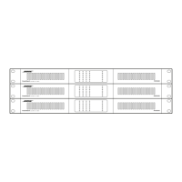
Figure 7. PowerShare PS604 amplifier rear panel
q INPUT – Balanced 12-pin Euroblock line-level input connector.
w USB – Connect the amplifier to a PC using a USB connection. This allows you to use the PC-based PowerShare Editor
software to configure the advanced features of the amplifier. The CONFIG DIP switch must be set to SOFTWARE to
configure the amplifer using the PowerShare Editor software. See the Software Interface section for more details.
e CHANNEL 1, 2, 3, 4 EQ – Each dial provides loudspeaker equalization presets per channel: DS 16, DS 40, DS 100, FS3B,
402, 802, MA12EX, RMU105, and RMU108. Use the Flat setting for FS3 Systems, or for loudspeakers that are not Bose
or that do not require EQ. When EQ is selected, the crossover and Vpeak and Vrms limiters for that loudspeaker are
automatically loaded. Use the PowerShare Editor software to adjust any of these parameters - see the Software Interface
section for more details. In Hi-Z output mode, a 50 Hz high-pass filter (HPF) is automatically added to the Hi-Z selected
outputs. The loudspeaker EQ is applied after the 50 Hz HPF.
r CONTROLCENTER – RJ-45 input connector for Bose® CC-1 ControlCenter zone controllers or CV41 4-to-1 Converter only.
Do not use this input to connect to a network.
t MUTE – Contact closure connection where a short across the mute connector will mute all outputs. This is the Normally
Open (NO) default state. The mute polarity can be inverted to Normally Closed (NC), where an open across the mute
connector will mute all outputs, using the PowerShare Editor software. See the Software Interface section for more
details.
y DIP Switches – A bank of switches used to set the amplifier configuration. All switches set to the left position is the
standard configuration.
• AUTO STANDBY – If enabled (ON), the amplifier goes into lower-power mode after twenty minutes without an input
signal. If in lower-power mode and an audio signal is detected, the amplifier will automatically wake and amplify
audio within 1 second. The default position is OFF.
• GLOBAL OUT – Sets the output capability to 70V or 100V for all outputs that have their OUTPUT DIP switch set to
Hi Z. In 70V mode, a 100 Vpeak limiter is automatically loaded. In 100V mode, a 141 Vpeak limiter is automatically
loaded. These are maximum values that can be lowered using the PowerShare Editor software if necessary. See the
Software Interface section for more details.
• CONFIG – In REAR mode, only the rear panel EQ settings are required to configure the amplifier. In SOFTWARE
mode, the PowerShare Editor software configures the amplifier, and the rear panel EQ switches are ignored. The
rest of the DIP switch settings are always independent of the PowerShare Editor software settings, as the software
does not interface with any other DIP switches. See the Software Interface section for more details.
• SENSITIVITY – Select 4 dBu or 12 dBu as the amplifier sensitivity for the line-level inputs.
• OUTPUT 1 – Select 70/100V high impedance output (Hi Z) or 4-8 Ω low impedance output (Low Z) for OUTPUT 1.
• OUTPUT 2 – Select 70/100V high impedance output (Hi Z) or 4-8 Ω low impedance output (Low Z) for OUTPUT 2.
• OUTPUT 3 - Select 70/100V high impedance output (Hi Z) or 4-8 Ω low impedance output (Low Z) for OUTPUT 3.
• OUTPUT 4 - Select 70/100V high impedance output (Hi Z) or 4-8 Ω low impedance output (Low Z) for OUTPUT 4.
u OUTPUT ATTENUATION 1, 2, 3, 4 – Output attenuators for each output. Turn the attenuators clockwise to decrease
attenuation, and counter-clockwise to increase attenuation. Fully clockwise is 0 dB attenuation; fully counter-clockwise
is mute. If CC-1 zone controller(s) are used, then the CC-1 becomes the master volume control(s). The position of each
attenuator will determine the CC-1 zone controller range for that output. Set each attenuator to 0 dB attenuation to allow
each CC-1 zone controller to have full attenuation range. If the CC-1 is disconnected from the amplifier, then the output
attenuator becomes the active setting.
i OUTPUT – Inverted 8-pin Euroblock connectors for loudspeaker connections. Each channel can deliver up to 600 watts
regardless of load into 4 Ω, 8 Ω, 70V, or 100V. Outputs are not bridgeable.
o AC Inlet – Removing the AC cord when the amplifier is on is equivalent to powering down using the front panel power
switch, and is an acceptable power-down method.
PS604 Rear Panel
q u
y
e itw r o