g320661
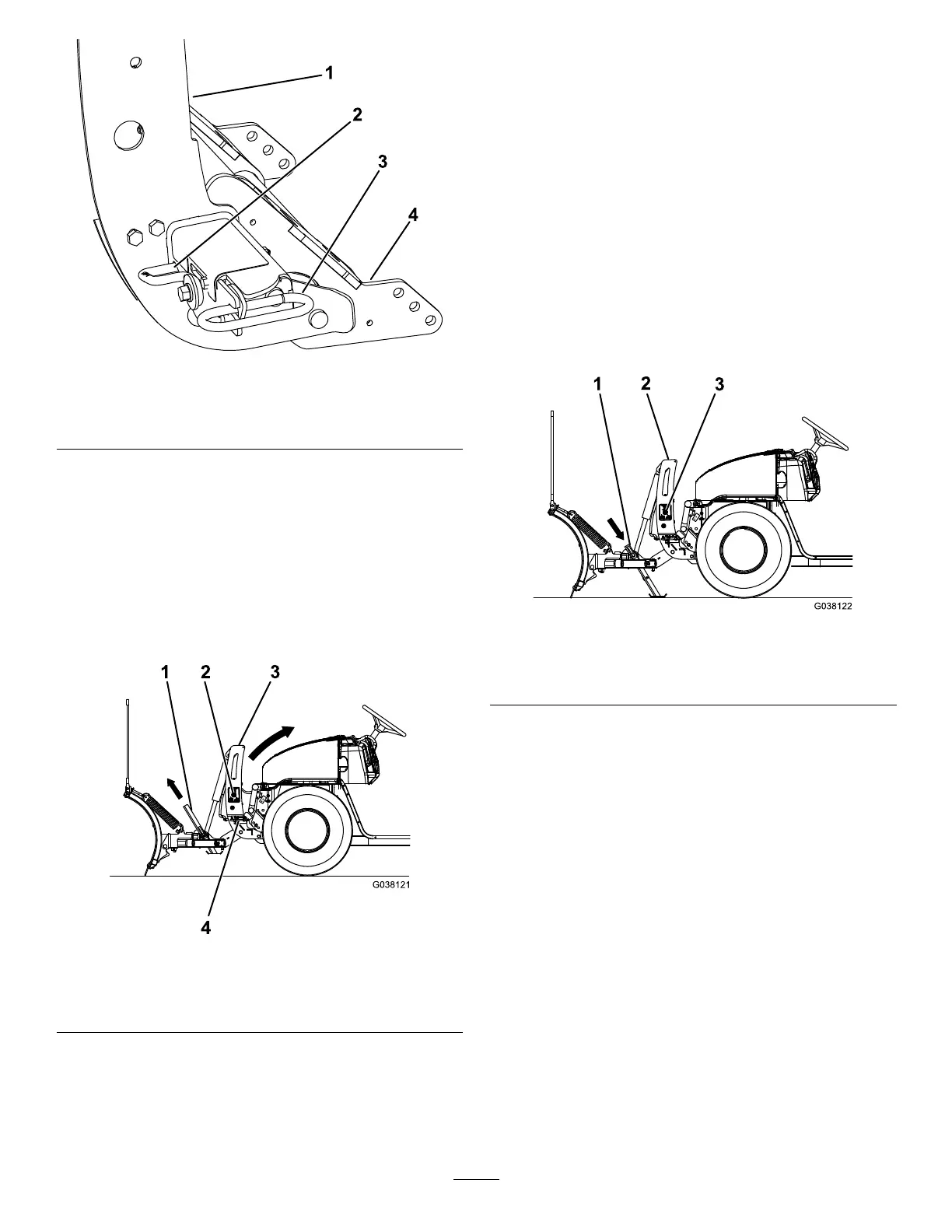
Figure19
1.Couplertower3.Couplerspringpin
2.Couplerlever
4.Pushbeamassembly
4.Removetheelectrical-plugdust-coversand
connecttheplowwireharnesstothevehicle
wireharness(Figure18).
5.PushtheSmartHitch2switchonthesideofthe
couplertowerupwardandraisethetoweruntil
thecouplerspringpinssnapin(Figure20).
Note:ForplowswithouttheSmartHitch2,
manuallypushthecouplertowertowardthe
vehicleuntilthespringpinssnapin.
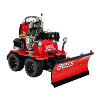
g038121
Figure20
1.Kickstand
3.Couplertower
2.SmartHitch2switch4.Couplerspringpin
6.Ensurethatbothcouplerspringpinshavefully
engagedthecoupler(Figure19).
Note:Movethecouplertoweruntilthespring
pinsengagecompletely.
7.Pullthekickstandspring-pinoutwardandraise
thekickstand,thenreleasethespringpinto
secureit(Figure20).
RemovingtheSnowplow
Note:Thevehiclemustberunningbeforestarting
thisprocedure.
1.SwitchtheheadlighttoggleswitchtotheTRUCK
position.
2.ActivatetheFLOATfeatureonyourplow
controller.
3.Pullthekickstandspringpinoutwardandlower
thekickstand,thenreleasethespringpinto
secureit(Figure21).
g038122
Figure21
1.Kickstand
3.SmartHitch2switch
2.Couplertower
4.TurntheleversonthecouplerstotheOFF
position(Figure22).
14