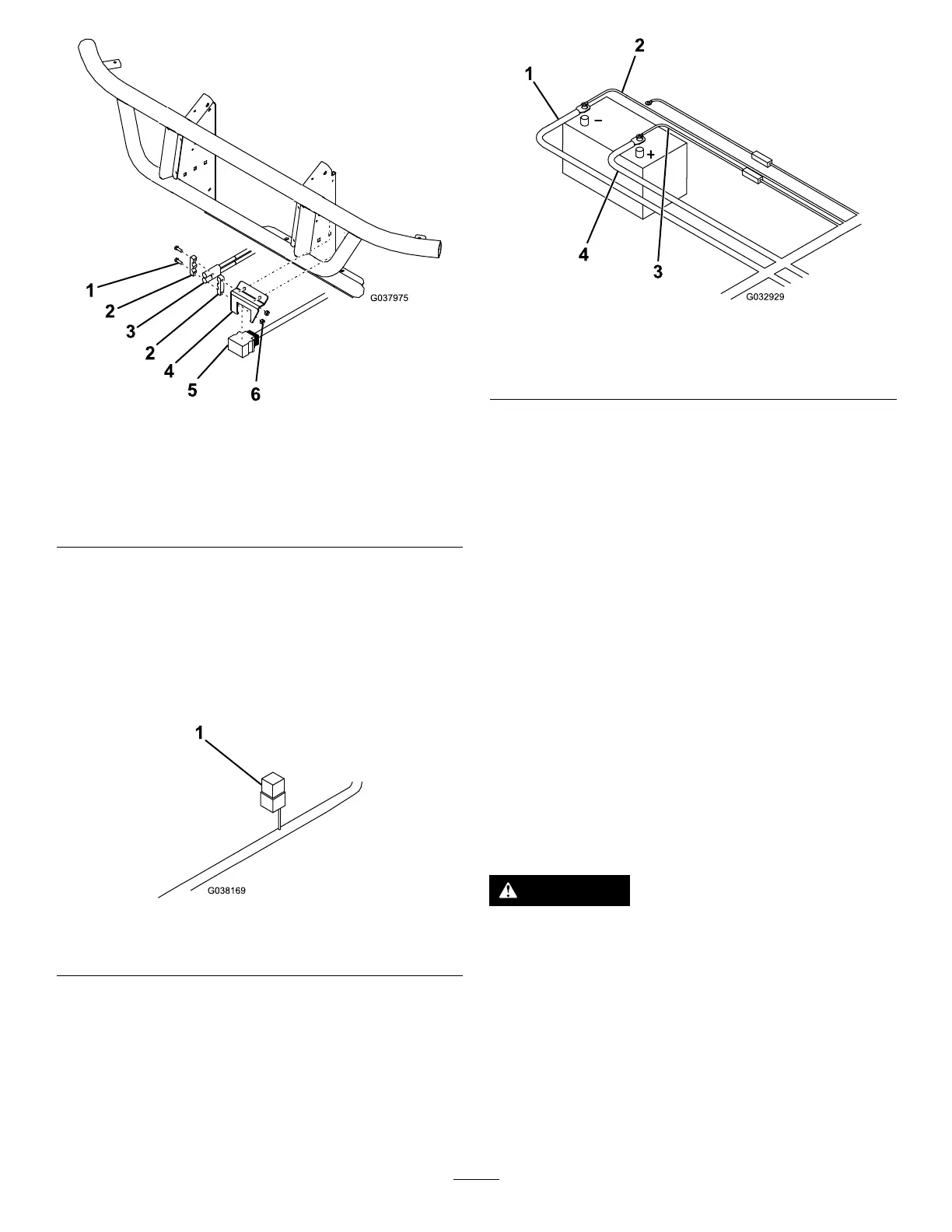
g037975
Figure11
1.Bolt
4.Controlharnessmounting
bracket
2.Power/Groundconnector
bracket
5.Plowconnector
3.Power/groundconnector
6.Nut
13.Mounttheblackandredpower/ground
connectortothecontrolharnessmounting
bracket(Figure11).
14.Mounttherelaypackunderthehoodusing1
sheet-metalscrew(Figure12).
Note:Ensurethattherelaypackismounted
intheuprightposition.
g038169
Figure12
1.Relaypack
15.Connecttheblackpower/groundcabletothe
negative(-)batteryterminal(Figure13).
g032929
Figure13
1.Blackpower/groundcable3.Redfusedwire
2.Brownwire4.Batterycable
16.Connectthebrownwiretothenegative(-)
batteryterminal(Figure13).
17.Connectthefreeendofthebatterycabletothe
positive(+)batteryterminal(Figure13).
18.Connectthered,fusedwiretothepositive(+)
batteryterminal(Figure13).
19.Secureallwiringinapositionthatavoidshotor
movingpartsusingcableties.
MountingthePlow
Controller
MountingtheSmartTouch2™
Controller
Note:Mountthecontrollerinthecabinadryarea
whereitdoesnotinterferewithvehicleoperationor
visibility.
Important:Donotinstalltheswivelmountwhen
temperaturesarebelow16°C(60°F).
DANGER
Thecontrollercouldcauseseriousinjuryif
contactedduringacrash.
Mountthecontrollerinalocationthatvehicle
occupantswillnotcontactduringacrash.
1.Determinethemountinglocationforthe
controller.
2.Cleanthelocationwiththeprovidedalcohol
wipeanddryitwithaclothorpapertowel.
3.Cleanthebackoftheswivelmount(Figure14)
withthealcoholwipeandthendryit.
10