Setup
Determinetheleftandrightsidesofthemachinefrom
thenormaloperatingposition.
InstallingthePushFrame
andCoupler
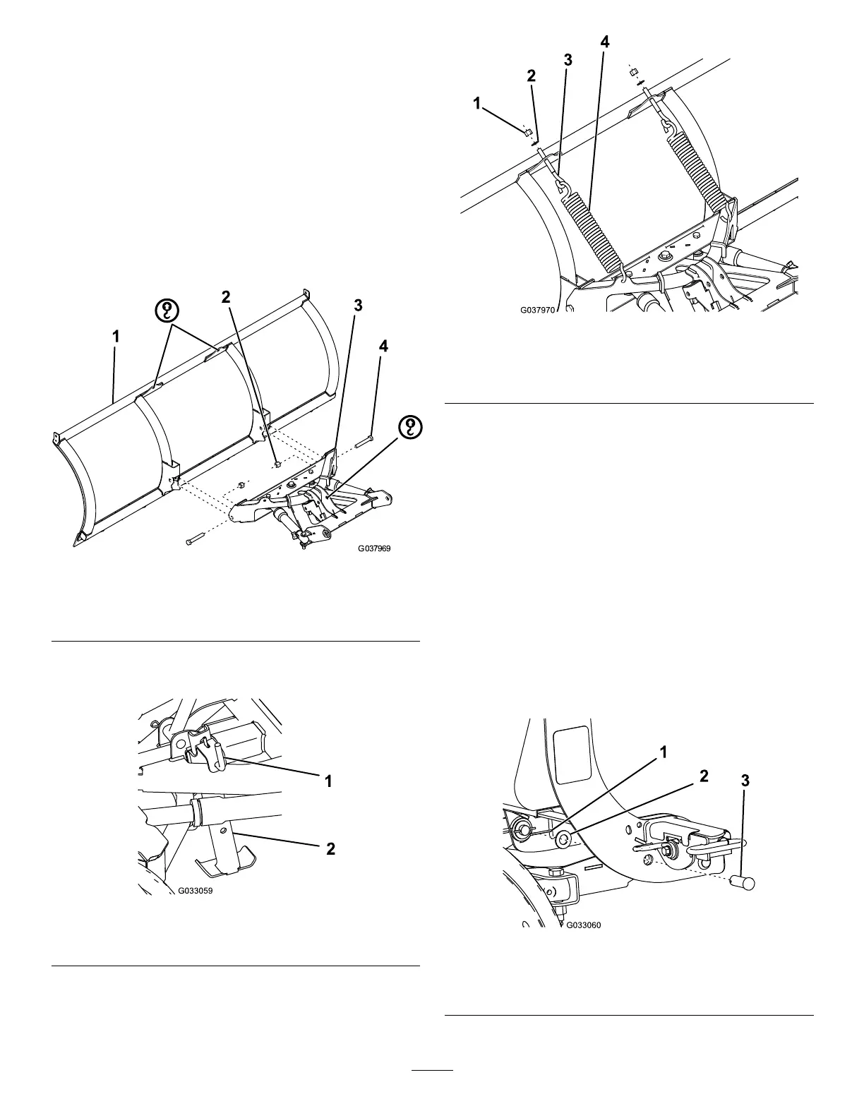
1.Attachthefrontofthepush-frameassembly
totheplowbladeusing2bolts(5/8inch)and
self-lockingnuts(Figure1).T orquetheboltsto
153N∙m(113ft-lb).
g037969
Figure1
1.Plowblade
3.Pushframeassembly
2.Self-lockingnut4.Bolt(5/8inch)
2.Pullthekickstand-springpintoreleaseand
lowerthekickstand(Figure2).
g033059
Figure2
1.Kickstandspring-pin2.Kickstand
3.Hookthe2tripspringsthroughtheholesonthe
push-frameassembly(Figure3).
g037970
Figure3
1.Self-lockingnut
3.Eyebolt
2.Washer4.Tripspring
4.Hooktheotherendsofthetripspringsto2
eyebolts(Figure3).
5.Insertthethreadedendoftheeyeboltsthrough
theholesontheplowbladeandsecurethem
using2washers(1/2inch)and2self-locking
nuts(Figure3).
6.Tightentheself-lockingnutsuntilthereisagap
of0.8mm(1/32inch)betweenthetripspring
coils.
7.Alignthepivotholesofthecouplertowerwith
thepivotholesonthepush-frameassembly,and
securethemwith2pivotpins,2atwashers
(3/4inch),and2cotterpins(Figure4).
Note:Makesuretospreadtheendsofthe
cotterpins.
g033060
Figure4
1.Cotterpin
3.Pivotpin
2.Flatwasher
6