8.Securetherodendoftheliftcylindertothe
push-frameassemblyusingaclevispinand
hairpincotter(Figure5).
g320666
Figure5
1.Clevispin3.Liftcylinder
2.Hairpincotter
4.Couplertower
9.Securethefreeendoftheliftcylindertothe
couplertowerusingaclevispinandhairpin
cotter(Figure5).
InstallingtheHydraulic
Hoses
1.Removetheplugfromthelowerportonthelift
cylinder.
2.Usingthreadcompound,installa90°ttingto
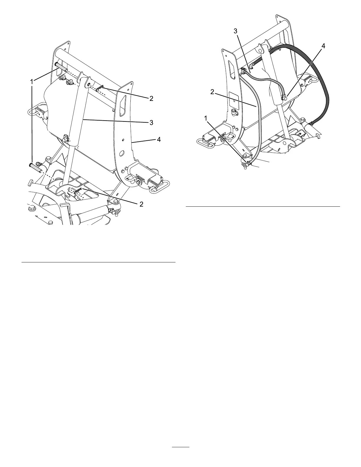
thelowerportontheliftcylinder(Figure6).
g320665
Figure6
1.90°tting3.39cm(15-1/2inch)hose
2.76cm(30inch)hose
3.Installthe39cm(15-1/2inch)hydraulichoseto
themiddlettingonthehydraulicshelfandthe
previouslyinstalled90°tting(Figure6).Turn
thettinguntilitisngertight,thenturnit2to
3moretimes.
Important:Donotovertighten.
4.Usingthreadcompound,installa90°tting
totherightanglecylinderlocatedonthe
push-frameassembly(Figure6).
Note:Thettingshouldbeinstalledata45°
anglepointingforward.
5.Installthe76cm(30inch)hydraulichoseto
therightttingonthehydraulicshelfandthe
previouslyinstalled90°tting(Figure6).Turn
thettinguntilitisngertight,thenturnit2to
3moretimes.
Important:Donotovertighten.
6.Repeatsteps4and5ontheleftside.
7.Removetheplugontheupperttingonthelift
cylinder,andinstallthebreathervent.
7