g320661
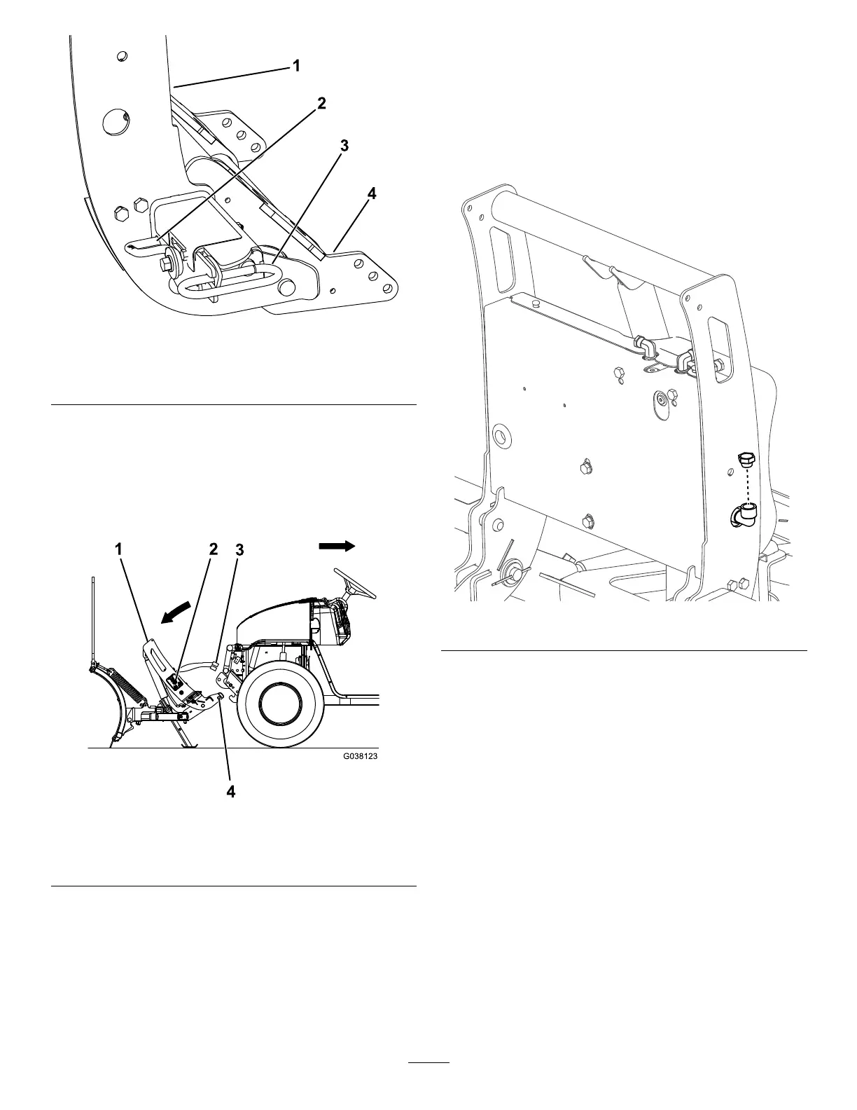
Figure22
1.Couplertower3.Couplerspringpin
2.Couplerlever
4.Pushbeamassembly
5.PushtheSmartHitch2switchonthesideofthe
couplertowerdownwardandlowerthetower
completely(Figure23).
Note:ForplowswithouttheSmartHitch2,
manuallypushthecouplertowerawayfromthe
vehicleuntilthespringpinsrelease.
g038123
Figure23
1.Couplertower
3.Plowwireharness
2.SmartHitch2switch
4.Lowerpin
6.Disconnecttheplowwireharnessfrom
thevehiclewireharnessandsecurethe
electrical-plugdust-covers(Figure23).
7.Slowlybackthevehicleawayfromthesnowplow.
CheckingtheHydraulic
FluidLevel
1.Withtheplowmountedtothevehicle,lowerthe
plowtothegroundandensurethatitisinthe
straightposition.
2.Cleantheareaaroundthellcap(Figure24).
g320664
Figure24
3.Removethellcapfromthehydraulicreservoir
(Figure24).
4.Ensurethattheuidcomesuptothebottomof
thellelbow.Ifitdoesnot,addmorehydraulic
uid;refertoAddingHydraulicFluid(page15).
5.Installthepreviouslyremovedllcap.
AddingHydraulicFluid
1.Ensurethattheliftcylinderiscompletely
collapsed.
Important:Donotmanuallypullthetower
down.Thiscancauseanairpockettoform
inthehydraulicsystemanduidtospillout
oftheinternalllercap.
2.Cleantheareaaroundthellcap(Figure24).
3.Removethellcapfromthehydraulicreservoir
(Figure25).
15