Note:Somevehiclesrequireabatterycable
extensionkit.ContactyourAuthorizedBOSSDealer
formoreinformation.
1.Parkthemachineonalevelsurface,shutoffthe
engine,waitforallmovingpartstostop,engage
theparkingbrake,andremovethekeyfromthe
ignitionswitch.
2.Pulltheplowcontrollerconnectorandblack/red
wireunderthehoodandintothevehiclecab
(Figure9).
g038119
Figure9
1.Self-tappingbolts
3.Plowcontrollerconnector
2.Dashbracket
3.Mounttheplowcontrollerconnectortothedash
bracket,andsecurethebrackettotheleftofthe
steeringwheelusing2self-tappingbolts(Figure
9).
4.Plugtheplowcontrollerintotheplowcontroller
connector.
5.Mounttheplowcontroller;refertoMountingthe
PlowController(page10).
6.Connecttheblack/redwiretoakeyed12V+
ignitionsource.
Note:Connectingthewiretoasourcethatis
notkeyedcancausethebatterytodrain.
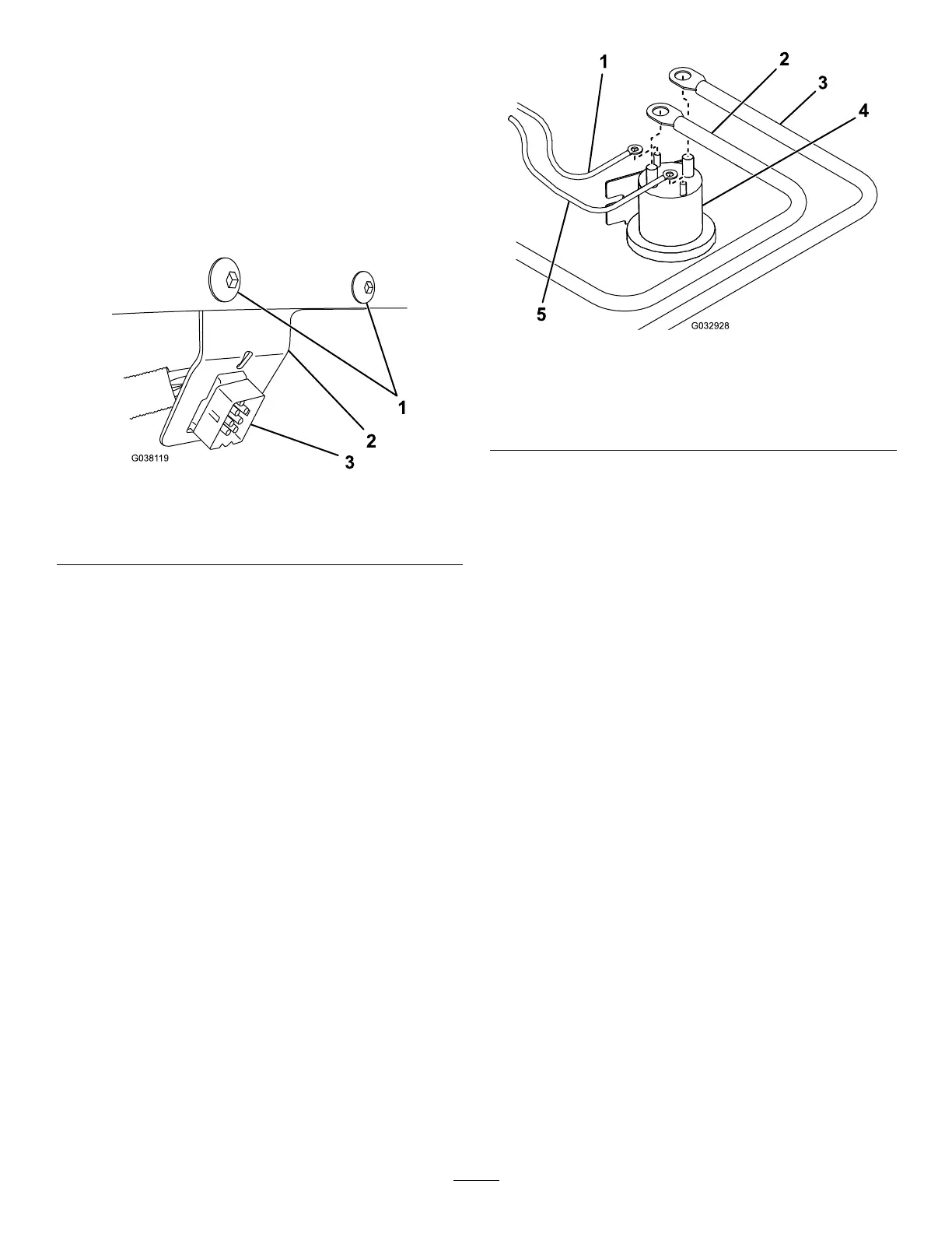
7.Connectthewhite/blackwirefromthewire
harnesstothesmallpostonthepumpsolenoid
(Figure10).
g032928
Figure10
1.White/blackwire
4.Pumpsolenoid
2.Batterycable5.Brownwire
3.Redpower/groundcable
8.Connectthebrownwirefromthewireharness
totheothersmallpostonthepumpsolenoid
(Figure10).
Note:Thewiresmaygooneithersmallpost,
butshouldnotshareapost.
9.Mountthepumpsolenoidunderthehoodof
thevehicle,ensuringthatitstaysinanupright
positionanddoesnotcontactthebody,hood,or
otherconductivematerialonthevehicle.
10.Connecttheredpower/groundcabletothelarge
postonthepumpsolenoid(Figure10).
11.Connectthebatterycabletotheotherlargepost
onthepumpsolenoid(Figure10).
Note:Thewiresmaygooneitherlargepost,
butshouldnotshareapost.
12.MounttheUTV-side,wire-harnessplow
connectortotheleftsideofthetoptube
ofthebumperusingthecontrol-harness
mounting-bracketand2self-tappingbolts
(Figure11).
Note:Youwillhavetodrill2holesinthe
bumpertubetomountthebracket.
9