A
C
Compresor
de aire
Filtro de aire
Engrasador
Regulador
depresión
BNT
15
RIVETER SETUP AND OPERATION
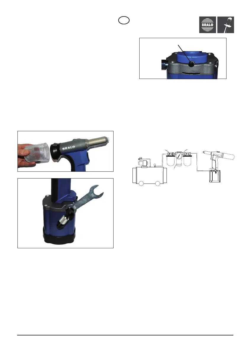
VACUUM CONTROL VALVE
www.bralo.com
1. Screw the spent mandrel collector onto the
riveting tool (Figure A).
2. Insert the air inlet fitting (Figure B).
3. Screw the hose onto the air inlet fitting.
4. Attach the hose to the air supply.
Remember that the operating pressure should
range between 6 and 7 bar!
5. Connect the appropriate nozzle.
6. Insert the rivet into the area of application, with
the rivet head perpendicular to it.
Do not hold the rivet with your fingers!
7. Squeeze the trigger. Make sure the spent
mandrel is ejected into the corresponding
collector.
If suction is required, turn right or left to adjust the
desired flow rate (Figure C). The vacuum system
automatically ejects the spent mandrel into the
collector.
If you choose to work without suction, the spent
mandrel will be transported to the collector by
gravity.
WARNING: Take care not to completely unscrew
the valve which would lead to loss of the piece.
From fully open to fully closed there is a total of 4
turns.
PRESSURE REGULATOR
This machine is designed to operate with a supply
of compressed air. It is necessary to use an air
pressure regulator; this ensures a longer life for
the tool and minimizes malfunctions. Make sure
the compressed air supply is dry and clean;
moisture and impurities can cause damage to the
tool.
MAINTENANCE
Clean the jaws every 5,000 rivets. Cleaning
prolongs its service life as dirt or metal particles
from the galvanised coating of the rivets can
accumulate.
You should consider replacing the jaws approxi-
mately every 100,000 rivets or when their grip on
the shank is incorrect.
CHANGING THE JAWS
1. Disconnect the air supply.
2. Unscrew the nozzle holder and the conical
portion of the jaw holder using num. 72 and No.
73 wrenches (Figure D).
3. Remove the jaws (Figure E)
4. Place the new jaws onto the conical part of the
jaw holder (Figure F) and screw on the conical part
again (Figure G). It is best to lubricate the jaws for
better tool performance, simply adding a few drops
into the nozzle.
5. Adjust the jaw holder with the keyed wrench:
BNT tool models 1,3 and 4 set to 57 mm; and BNT
models 2 and 5 set to 66 mm (Figure H).
EN
Figure A
Figure B
Figure C
valve
Air filter
Lubrication nipple
Pressure
regulator
Air
compressor
 Loading...