Page 16
RAMP INSTALLATION
Door Opening: Open the door(s)
fully and check the clear door
opening width dimension. Speci-
ÀHGPLQLPXPFOHDUGRRURSHQLQJ
width must be provided (see next
page).
Door(s) must open outward.
When closed, the door(s) should
align with and conform to the
outboard edge of the ramp pan
(rubber seal on bottom of door).
Minimum Clear Door Opening
'LPHQVLRQVDUHGHÀQHGDV
ÀQLVKHGGRRURSHQLQJLQFOXG-
LQJDQ\LQWUXVLYHGRRUMDPEV
headers, sills or hinges.
Obstructions: Any intrusive
obstructions within the door
opening or the ramp mounting/
operating area (such as seats,
molding, lights, brackets, etc.)
must be removed. Trim or
remove molding that creates an
uneven mounting surface should
be removed. The molding can
EHPRGLÀHGWRÀWDURXQGWKH
ramp pan horizontal border (lip).
7KHUHPXVWEHDPLQLPXP
clearance between the deployed
ramp assembly and the vehicle
ÁRRURUDQ\REVWUXFWLRQRQWKH
ÁRRUVXFKDVDUXEEHUVLOORU
threshold).
Floor Pocket
Outboard Support Tube:
Recommended Height can be
determined by using the chart
on the following page. Kneeling
Vehicles: Measured with sus-
pension lowered.
ADA: Installations with the
support tube positioned above
the recommended height from
ground level may not comply
with ADA ramp slope require-
ments.
7KHSRUWLRQRIWKHÁRRUZKHUH
the ramp mounts can range in
slope from 0° to 9.5°.
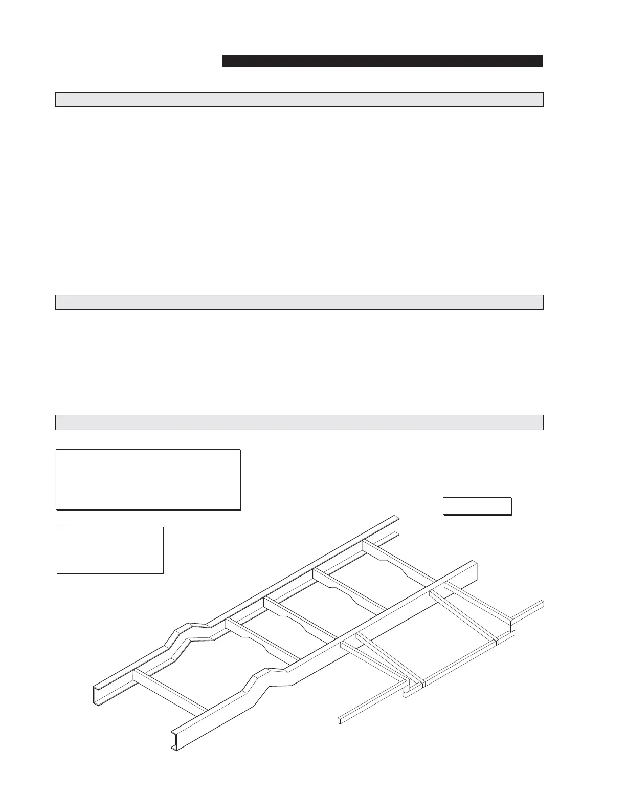
Chassis
SUPPORT TUBE
Floor Pocket
Framework
Outboard
Support Tube
Figure C
Note: Ramp assembly mounting hard-
ware and/or brackets are directly depen-
GDQWXSRQWKHYHKLFOHFKDVVLVDQG´ÁRRU
SRFNHWµFRQÀJXUDWLRQQRWVXSSOLHG
Structure: Minimum
1-1/2” x 2” steel tub-
ing (or equivalent).
Installation Requirements (continued)
Floor Pocket Framework