9
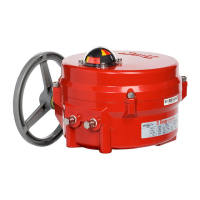
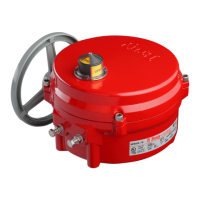
Series 70 Electric Actuator
Operation and Maintenance Manual
Heater
To prevent condensation from forming inside the
actuator, Bray offers an optional heater. The heater is
a PTC (Positive Temperature Coefficient) style which
has a unique temperature - resistance characteristic.
The heater self-regulates by increasing its electrical
resistance relative to its temperature. The heater does
not require external thermostats or switches to control
its heat output. It is constructed of a polycrystalline
ceramic, sandwiched between two conductors, and
wrapped inside a thermally conductive electrical
insulator.
Connect the heater wires to the terminal strip as
indicated on the wiring diagram.
NOTE: The heater must have a constant power supply
to be effective.
WARNING
The heater surface can reach temperatures in excess
of 200 degrees Celsius
Heater Kit Consists of:
1. Heater with flying leads
2. Heater Mounting Bracket
3. #10 pan head screw, Phillips drive
Tools required:
• For terminal wiring: Screwdriver, 3/16” tip flat blade
• For heater mounting screw: Screwdriver, No.1 Phillips
Installation Procedure
The heater is mounted through a hole provided in
the switchplate.
Before servicing unit, switch all power off at the service
panel and lock the service disconnecting means to
prevent power from being switched on accidentally.
When the service disconnecting means cannot be
locked, securely fasten a prominent warning device,
such as a tag, to the service panel.
Disconnect all power to the unit.
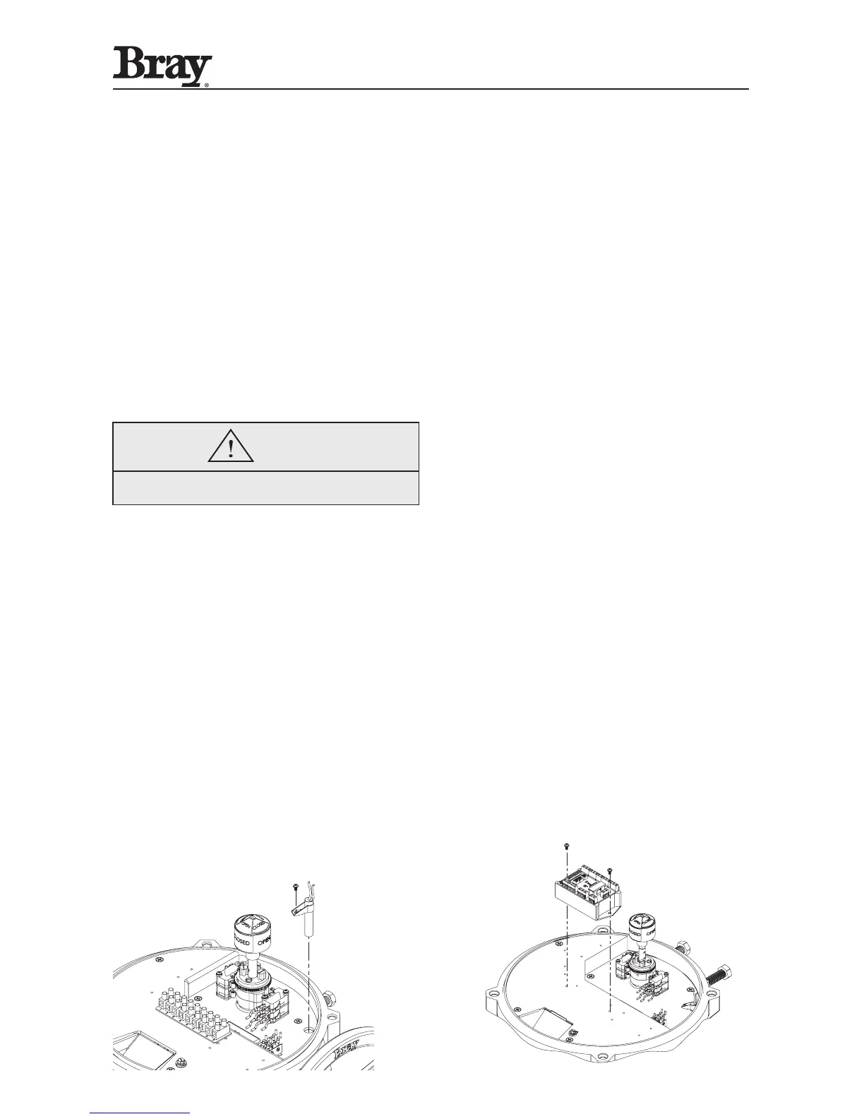
1. Place the heater snugly into its mounting bracket
until approx. 1/2 to 1” is left above the bracket as
shown in diagram.
2. Slip the heater into its mounting hole.
3. Align the fastening hole in the bracket with the
threaded screw hole in the plate. Fasten the heater
to the switchplate.
4. Connect the heater wires to the terminal strip as
indicated on the wiring diagram.
Servo-Pro Module
Servo kits can be field installed on any continuous
duty actuator (30, 60, or 110 sec. operation speed) to
provide proportional positioning in response to a control
signal. Intermittent duty actuators are not adaptable
for servo control.
Servo Kit Consists of:
1. One servo module
2. Four #6 cross drive pan head screw (two for servo,
two for feedback potentiometer)
3. One potentiometer assembly
4. Two #6 type A internal lockwashers (for pot)
5. One wiring diagram sticker for attaching to inside
of actuator’s cover
6. One wiring diagram sticker for servo units with
torque switches
Tools required:
• For actuator terminals wiring Screwdriver, 3/16”
flatblade
• For servo terminals: Screwdriver, No.1 Phillips
• For servo and pot mounting screws: Screwdriver, No.2
Phillips
 Loading...