7
Series 70 Electric Actuator
Operation and Maintenance Manual
Disassembly and Assembly
Tools required:
See Appendix A for a complete list of basic tools.
NOTE 1: Assembly is the opposite of removal.
NOTE 2: Pictures shown for Housing Size 6 are typical
for all sizes.
Procedure
WARNING
Turn off all power and lock out service panel before
installing or modifying any electrical wiring.
1. Disconnect motor wires from the main terminal strip
(motor neutral, open, and close).
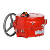
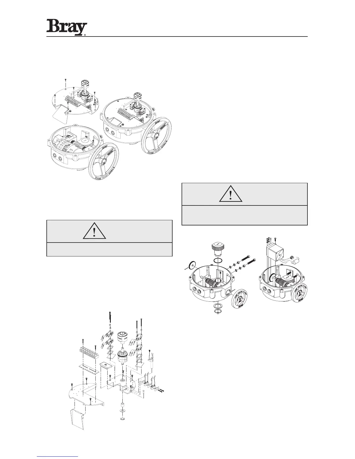
2. Remove the switchplate by unscrewing the seven
Phillips head mounting screws. The switchplate
should lift out as an assembly with the camshaft
attached.
3. The switchplate can be independently disassembled.
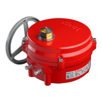
4. To remove the Gearmotor, first disconnect the motor
leads which run to the capacitor, and unscrew the
mounting screws for Housing Size 6 (two lower,
one upper) for other Housing Sizes (four lower, one
upper). The motor can now be removed vertically out
of the unit. Note: do not misplace the alignment pin.
5. To remove the worm shaft spur gear, remove the
spring pin using a 3/32” punch, then slide the gear
off the end of the worm shaft for Housing Sizes 6
and 12. Remove bowed E-clip retainer for Housing
Size 30-180.
6. To remove the output drive worm gear, back off
both mechanical travel stops. Remove the retaining
ring and thrust washer, then lift the output drive
worm gear out of its base.
7. The handwheel is held by a spring pin.
 Loading...