4
Series 70 Electric Actuator
Operation and Maintenance Manual
Manual Override Operation (Declutch-
able)
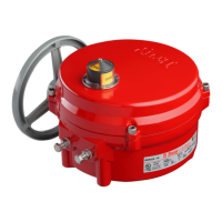
The manual override operates similar to a watch
adjusting knob. To engage the manual override, simply
pull the handwheel to its outermost position. A yellow
stripe is revealed for visual indication that the unit
cannot run electrically. The two handwheel positions,
engaged and disengaged, are held in place with the use
of spring plungers. The handwheel remains in position
until physically moved. Rotating the handwheel in the
clockwise direction will rotate the output shaft in the
same clockwise (closed) direction and vice-versa.
CAUTION
A label on the handwheel hub warns users not to
exceed a specific rim pull force, for each size of
actuator. If the rim pull force is exceeded, the roll pin
securing the handwheel onto the manual override
shaft is designed to shear, thus preventing more
serious internal gearing damage.
Pre-Installation Storage
Actuators are not weatherproof until properly installed
on the valve or prepared for storage. Bray cannot accept
responsibility for deterioration caused on-site once the
cover is removed.
NOTICE
Units are shipped with two metal screw-in plugs to
prevent foreign matter from entering the unit. To
prevent condensation from forming inside these
units, maintain a near constant external temperature
and store in a well-ventilated, clean, dry room away
from vibration.
For units with an internal heater, power should
be supplied to the heater via conduit entry and
appropriate sealing gland.
Store units on a shelf or wooden pallet in order to
protect against floor dampness.
Keep units covered to protect against dust and dirt.
Installation
Mounting to a Valve
All Bray Series 70 electric actuators are suitable for
direct mounting on Bray butterfly valves. With proper
mounting hardware, the S70 actuator can be installed
onto other quarter-turn valves or devices.
NOTICE
The standard mounting position for the actuator is to
orient the unit with its handwheel in a vertical plane
and parallel to the pipeline. If the actuator is to be
mounted on a vertical pipe, it is recommended that
the unit be positioned with the conduit entries on
the bottom to prevent condensation from entering
the actuator by way of the conduit. In all cases, the
conduit should be positioned to prevent drainage into
the actuator.
The actuator should be mounted to the valve as follows:
1. Manually operate the actuator until the output shaft
of the actuator is in line with the valve stem. If
possible, select an intermediate position (i.e. valve
disc/stem and actuator both half open).
2. Place the proper adapter, if required, onto the valve
stem. It is recommended that a small amount of
grease be applied to the adapter to ease assembly.
3. Mount the actuator onto the valve stem. It may be
necessary to swing or manually override the actuator
to align the bolt patterns.
4. Install the furnished mounting studs by threading
them all the way into the actuator base.
5. Fasten in place with the furnished hex nuts and
lock washers.
Field Wiring
WARNING
Turn off all power and lock out service panel before
installing or modifying any electrical wiring.
Each actuator is provided with two (2) conduit entries
(one for power and one for control).
1. The motor full load current is noted on the nameplate
of the actuator. The terminal strip will accept wire
sizes ranging from 14 to 22 AWG (14 to 24 AWG
for the servo).
NOTICE
18 AWG minimum wire is recommended for all field
wiring.
Note that the optional heaters use approximately 0.5
amps at 110 volts.
2. All actuators have their applicable wiring
diagram attached to the inside of the cover. Field
wiring should be terminated at the actuator terminal
strip in accordance with this wiring diagram.
 Loading...